Can I fix this LED driver?

pwd

10 kW
Joined
Oct 11, 2011
Messages
799
Location
Ontario, Canada
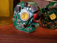
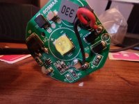
I have these LED drivers which both failed after less than 5 hours each. My estimate is that they failed because they are rated for an input voltage of 10-80VDC but my pack is 86.1V full. I didn't notice when the first one failed but the second one failed when I turned it on via a simple on-off switch.

Can these boards be repaired and improved to handle the 86V input without popping? :flame:
 

Attachments

  • IMG_20211124_103401409_HDR.jpg
    IMG_20211124_103401409_HDR.jpg
    381.7 KB · Views: 295
  • IMG_20211124_103351292_HDR.jpg
    IMG_20211124_103351292_HDR.jpg
    328.5 KB · Views: 295
The two most likley parts to fail are the small IC chip and the FET. You'd need to know what those parts are, and find their specs, to see if they are designed to handle the voltages your system makes (including any spikes that occur at any point in operation/etc.).

If they aren't, then you'd need to find equivalents that *can* handle those voltages.

FETs are usually easy enough to find, but that IC might be harder. You might have to use the original, and add a DC-DC converter (that does handle the voltages well, at the currents the LED driver board needs) between the system and the board.


The diodes could also be underrated but that's much less likely.
 
It may be easier to get a buck converter, and either use those LEDs or get some with 12V drivers and run them off the converter. The XML Cree LEDs use about 10W-15W, so you should be able to drive 2 or 3 off of one $5-$6 buck converter.
 
Thanks for your input guys. I going to choose a suitable DC - DC converter and try feeding the boards 12V. I have ordered some replacement boards/drivers for this light instead of attempting to repair the existing ones.
 
Look at how the solder pooled around R4 and R5. This suggests to me that the board over-heated by a lot. Maybe R4 and R5 turned into surface mount heating elements and gave up. Other than the solder pooling did they crack too?

If you insert a buck converter to lower the DC input to the LED built-in buck converter it will dissipate heat between the two boards. Buck converters sometimes have a heat-sink recommendation, or a built in heatsink, so you may want to give this extra attention.
 
mintycrayon said:
Look at how the solder pooled around R4 and R5. This suggests to me that the board over-heated by a lot. Maybe R4 and R5 turned into surface mount heating elements and gave up. Other than the solder pooling did they crack too?

If you insert a buck converter to lower the DC input to the LED built-in buck converter it will dissipate heat between the two boards. Buck converters sometimes have a heat-sink recommendation, or a built in heatsink, so you may want to give this extra attention.

Sharp eye, and easy to see on the second board now that you pointed that out. And based on the traces, it looks like those two resistors carry all of the current.
 
Back
Top