CYC x1 pro through CA3 with TQ sensor and Domino help

Ham

10 kW
Joined
Feb 18, 2016
Messages
501
Hi All,

I am in the process of rewiring the x1 pro 2 to run through the CA3 and am struggling to understand the settings required on the CA3 to get the torque sensor to work.

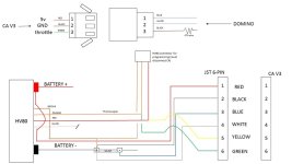
I am at the stage where I think the wiring to the CA3 is correct (as per a previous thread where someone else has done it), red, black, white and green wires from cyc torques sensors to white (10v), black (ground), green( torque) and yellow (RPM) respectively on the CA3 torque sensor plug. so

cyc red to ca3 white, black to black, white to green, green to yellow

I have tried to set the CA3 torque sensor up as "custom", 2 wire, 32 poles (I believe the CYC torque sensor is 32 poles but may be wrong). The CA menu shows voltage values as changing, direction as correct but only one side of the P/D indicators moves when rotating (P side).

I get no motor response at this stage...not sure why yet...any help is greatly appreciated.

Also trying to figure out the domino wiring, I understand I need to put a 1k resistor somewhere in the mix but wiring diagrams are jibberish to me I am afraid!
 
Your domino may be the cause of your issues. The full throttle max output voltage is near 5 volts and may shut down a controller because it’s exceeding it’s voltage maximum for throttle. On the other end you have more than 0 volts at a standstill which may make a controller not work. I did my research years ago and went with a 100k trimpot, an adjustable potentiometer. It’s used in-line on the input voltage, to lower it. It is adjusted so the controller doesn’t cut out at full throttle. I’ve done this on two domino, cyclone ebikes.
 
Thanks,

I haven't got to the stage of connecting the domino yet...still working out where the resistor needs to go so not seeing how that can cause issues just yet:)
 
If the CYC is designed for a hall throttle, not a pot (like domino uses), then you put two resistors on the domino, one from the domino's 5v line to the actual 5v line and one on the domino's ground to the actual ground, of the right value to create a voltage divider with the domino's own resistance.

THe divider needs to be such that the domino's "ground" wire reads just below the CYC's lowest throttle start voltage. And the domino's "5v" wire reads at the CYC's maximum throttle response voltage. As long as the domino signal covers it's entire range like a regular pot would, that will cause the domino's output to cover the full range of the CYC's input response without causing any errors. If it doesn't, you can change the resistor at "top" or "bottom" as needed to fix this.

If you don't want to calculate the values of these resistors, and find matching ones, or need fine adjustment ability, just use two small 5kohm potentometers instead, and wire them with one "outside" leg not connected, and the other to the domino's wires as noted above. Then the middle leg of each goes to the actual 5v or ground, respectively. Then simply adjust the pots while checking the voltage at teh domino itself to be sure they are set correctly. I recommend using the small blue multiturn "trimpots" like the ones in teh first picture here, because you can glue them down wherever is handy within the wiring harness, etc.:
https://www.robotroom.com/Trimpots.html
but you can use any small pot.
 
Ham said:
I am in the process of rewiring the x1 pro 2 to run through the CA3 and am struggling to understand the settings required on the CA3 to get the torque sensor to work.

I am at the stage where I think the wiring to the CA3 is correct (as per a previous thread where someone else has done it), red, black, white and green wires from cyc torques sensors to white (10v), black (ground), green( torque) and yellow (RPM) respectively on the CA3 torque sensor plug. so

cyc red to ca3 white, black to black, white to green, green to yellow

I have tried to set the CA3 torque sensor up as "custom", 2 wire, 32 poles (I believe the CYC torque sensor is 32 poles but may be wrong). The CA menu shows voltage values as changing, direction as correct but only one side of the P/D indicators moves when rotating (P side).

I get no motor response at this stage...not sure why yet...any help is greatly appreciated.

First, if you press the CA's left button once, you should get to the diagnostic screen. Are any of the letters on the lower left capitalized, or are they all lower-case? These are limit flags, and anything capitalized means the CA is reading that value as over a limit in some menu.

We'd need to know your complete CA setup for all menus to know what might be causing a problem, because many settings interact with each other. If you can save your settings off of your actual CA as a file with the CA setup utility, and tell us which firmware it is for (listed on the CA startup screen), we can load that into the setup program and see your settings.


I don't know what color on your CYC is which signal. Can you post a list of CYC signal names for each of it's wire colors, to help us match those to the right CA signal?

What torque sensor does the CYC use, what is it's power supply voltage range, and what does it output for minimum torque, maximum torque, etc? Some use an output voltage range that starts in the middle and goes positive or negative from there, some start at zero for no torque and goes up to 5v for max torque. Need to know this so you can set the torque sensor up in the CA correctly and calibrate it.

What cadence sensor does it use, and what signal type does it create? Some have two separate signals, and some have only one, and some create different signal patterns from others. Need to know this to setup the cadence sensor in the CA correctly.
 
Thank you. I will have a look into the diagnostic screen.

As an update:

I have managed to get the torque sensor to activate the motor...I am using a Castle hv160 controller, I forgot to mention that as I was stuck on this being a cyc conversion but I guess in reality it is only the cyc motor and reduction unit being used! Foolish me.

The castle controller needed re programming to airplane mode and a few other parameters regarding cut offs and motor start up. It is all on the bench right now but it appears the torque sensor wiring is correct enough to work on the bench.

Having realised this is not using the cyc bac controller and thus not programmed for a hall throttle, I am now wondering if I need to bother adding a resistor for the castle controller paired with CA3?

I think I read that the resistor on the Domino is for controllers set for hall throttles that have a different voltage range setting lower than 4.2v? Seeing as how I can set the voltage range and fault voltage for the domino within the CA3 am I correct in thinking I don't need to add the resistor?

Thanks guys
 
Ham said:
The castle controller needed re programming to airplane mode and a few other parameters regarding cut offs and motor start up.
I don't know how much "smarts" the CC has but most of the time when using the CA to do controls, limiting, etc., it is easier to ensure the controller is setup to be as "dumb" as possible, so that you know that any limiting that's going on is the result of your CA settings, making it easier to troubleshoot problems. ;)

Without knowing *all* of your CA settings, I can't do much to help you with any of that.


It is all on the bench right now but it appears the torque sensor wiring is correct enough to work on the bench.
Just to be clear, is the torque sensor wired to the controller, or to the CA?


Having realised this is not using the cyc bac controller and thus not programmed for a hall throttle, I am now wondering if I need to bother adding a resistor for the castle controller paired with CA3?
AFAICR, RC type controllers (like the CC) are expecting a PWM throttle signal, rather than a voltage throttle signal. The CA can output either type, which you setup in the throttle out menus. If the CC does need PWM, just set the CA to do that. If the CC needs voltage throttle, leave the CA in voltage throttle mode.

Then, you need to set the CA's throttle output voltage ranges to whatever the CC expects. If the CC has it's own throttle input range settings, you need to be sure the CA and CC match.


I think I read that the resistor on the Domino is for controllers set for hall throttles that have a different voltage range setting lower than 4.2v? Seeing as how I can set the voltage range and fault voltage for the domino within the CA3 am I correct in thinking I don't need to add the resistor?
If you are using the CA to read the throttle and send that to the CC, then you simply need to set the CA throttle input to read the range the Domino outputs. No extra hardware is needed.

It would be helpful if you drew up at least a block diagram of your system, both so we know what you are wiring where, to help you figure things out, and so that you yourself can refer to it whenever needed. (for example, if I'd known you were not using the domino to run the controller directly, I could have skipped the whole resistor advice post and just said what I did above. ;) )

It would also be helpful if you would provide both your complete CC settings and your complete CA settings. If we don't know how you have them setup, we can't help you figure out which things are causing you problems.

The less information we have, the more guessing we have to do and the less useful the help we provide will be.
 
You Sir are most helpful!

Thank you.

I have basically set the throttle up as per my old tangent set up now I have found those details! https://dave-dubose.squarespace.com/faq

All the electricals are the same, thankfully.

I now have it all up and running on the bench, throttle included...I just copied Dave's wiring diagram as linked.

Both the torque sensor and throttle now go directly through the CA3. I popped a 470ohm resistor in line as per Daves wiring diagram. No clue if it was really needed or not but all seems to work.

Now I am curious about Dominos little microswitch and before I go tidying and closing cables and wires up wondered if I can use it for anything useful...any ideas?

Safety cut off somehow?

Thanks again for all your help thus far
 
Ham said:
You Sir are most helpful!
Thank you.
I try. ;)

I have basically set the throttle up as per my old tangent set up now I have found those details! https://dave-dubose.squarespace.com/faq

All the electricals are the same, thankfully.

I now have it all up and running on the bench, throttle included...I just copied Dave's wiring diagram as linked.
This one?
ca setup.jpeg

If the controller you are using has the same throttle input range as the tangent's controller, then using the same settings in the CA will work for it. If it does not, then you should change the CA's throttle out setup menu settings to match your controller's requirements, so that you can get the full operational range of the controller matched to your throttle movements.


Both the torque sensor and throttle now go directly through the CA3. I popped a 470ohm resistor in line as per Daves wiring diagram. No clue if it was really needed or not but all seems to work.
It shouldn't be needed. A resistor in the ground line "lifts" the ground of the domino so that it can't ever actually go to zero volts. If it were directly connected to a controller that is meant for a hall throttle instead, then that could be necessary to prevent a "dead zone" at the bottom of the throttle rotation range. It can also be used to cause a system to always be on just a little bit, kind of like the "Freewheeling" option in the Phaserunner setup.

The CA has completely adjustable input and output ranges, so no such modifications are necessary. If a modification like that is used, the CA throttle in settings menu needs to be adjusted for the low end of the throttle range to account for the voltage that will always be present there from that resistor. (otherwise, the system will always be "on" a little bit, always feeding some power to the motor (even if the motor doesn't turn), assuming the throttle out settings menu is simply setup to provide the normal full throttle range your specific controller uses).


Now I am curious about Dominos little microswitch and before I go tidying and closing cables and wires up wondered if I can use it for anything useful...any ideas?

Safety cut off somehow?

If that is the switch that opens when the throttle is at it's zero position, not being moved by the rider, it's meant to be wired to disable the controller or the throttle whenever you are at zero throttle.

The simplest way to use it, if it has two separate wires for the switch not connected to anything else, is to wire it in series iwth the 5v to the throttle. Then there is no throttle signal at all, "guaranteed", unless you twist the throttle past the microswitch's closing point, because then the only two wires connected to the throttle signal are signal and ground, so it keeps the throttle at zero. Even a broken throttle ground wire to the throttle itself cant' cause runaway operation when you aren't operating the throttle under this condition.
 
Hmmm that's quite a bit for me to get my head around! I will have to do some more reading to fully understand if and how to implement the micro switch.

Thanks again, I am sure I will have more questions at some point!
 
If anyone is still following this thread then I have the bike up and running.

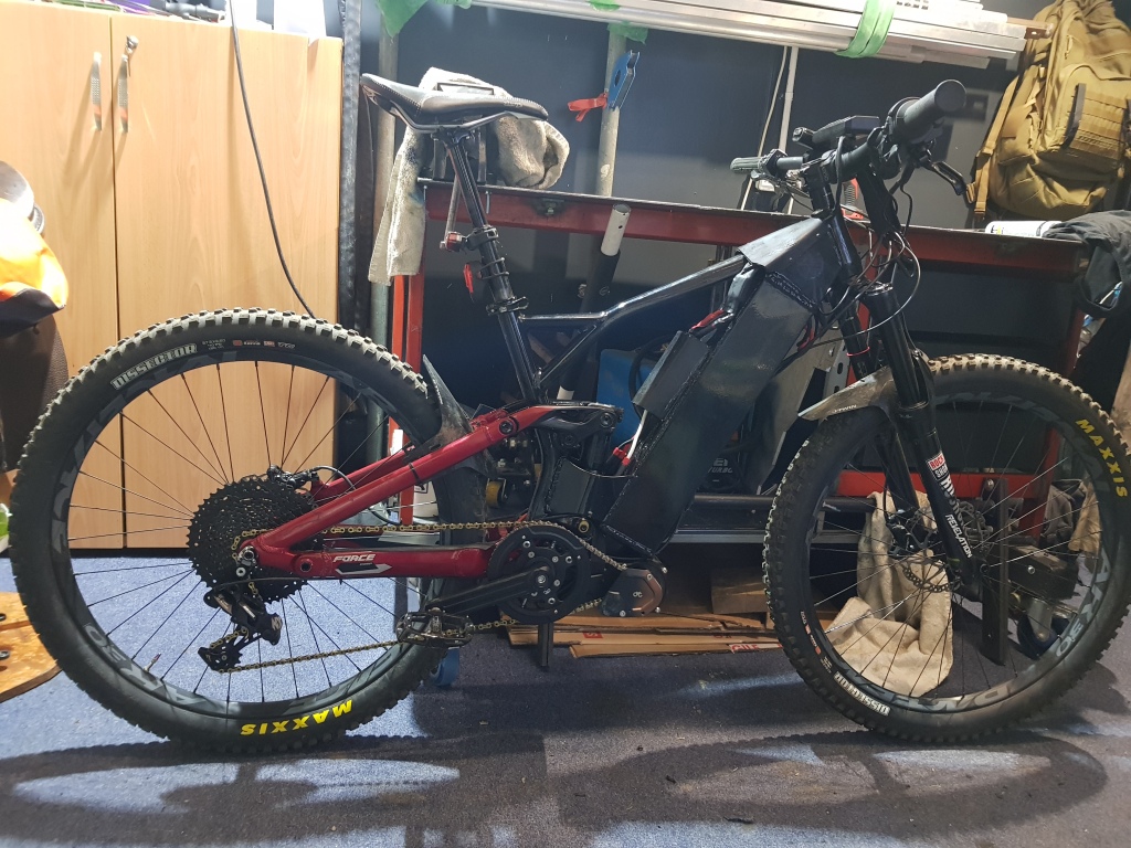
Three presets controlled by the handlebar switch : 500w (no throttle), 1000w and 5000w PAS and throttle working. Much fun was had over a 20 mile test day, nothing broke. Win.

I have a few issues to work through:

Throttle only from dead stop in full power mode jerks on and off if I am in a high gear, I have seemingly got around this with dropping AGain down from 100 to where the chugging stops at about 40 but have as a result lost that "blast off" sensation. Minor annoyance really as it makes it easier to ride but the similar set up I had with Tangent and an astro 3220 with AGain at 100 upwards was just fine from dead stop. Weird.

Also weirdly it only does this in 5000watts mode. The 1000w mode does not really have this chugging on off issue even at AGain of 100.

Now I am back up to pulling bigger amps I am going to be chasing down the old voltage sag issue. Much of the system is using xt90s and also the grin potted 100amp shunt with it's tiny 10awg wires which I had as a spare to get started. Over the next month or so I will slowly swap out xt 90s for xt150s and upgrade the shunt and cabling there.

Still also trying to get my head around the actual real world difference between current controlled throttle and pass thru mode?? Both seem very similar whizzing around the yard testing them...
 
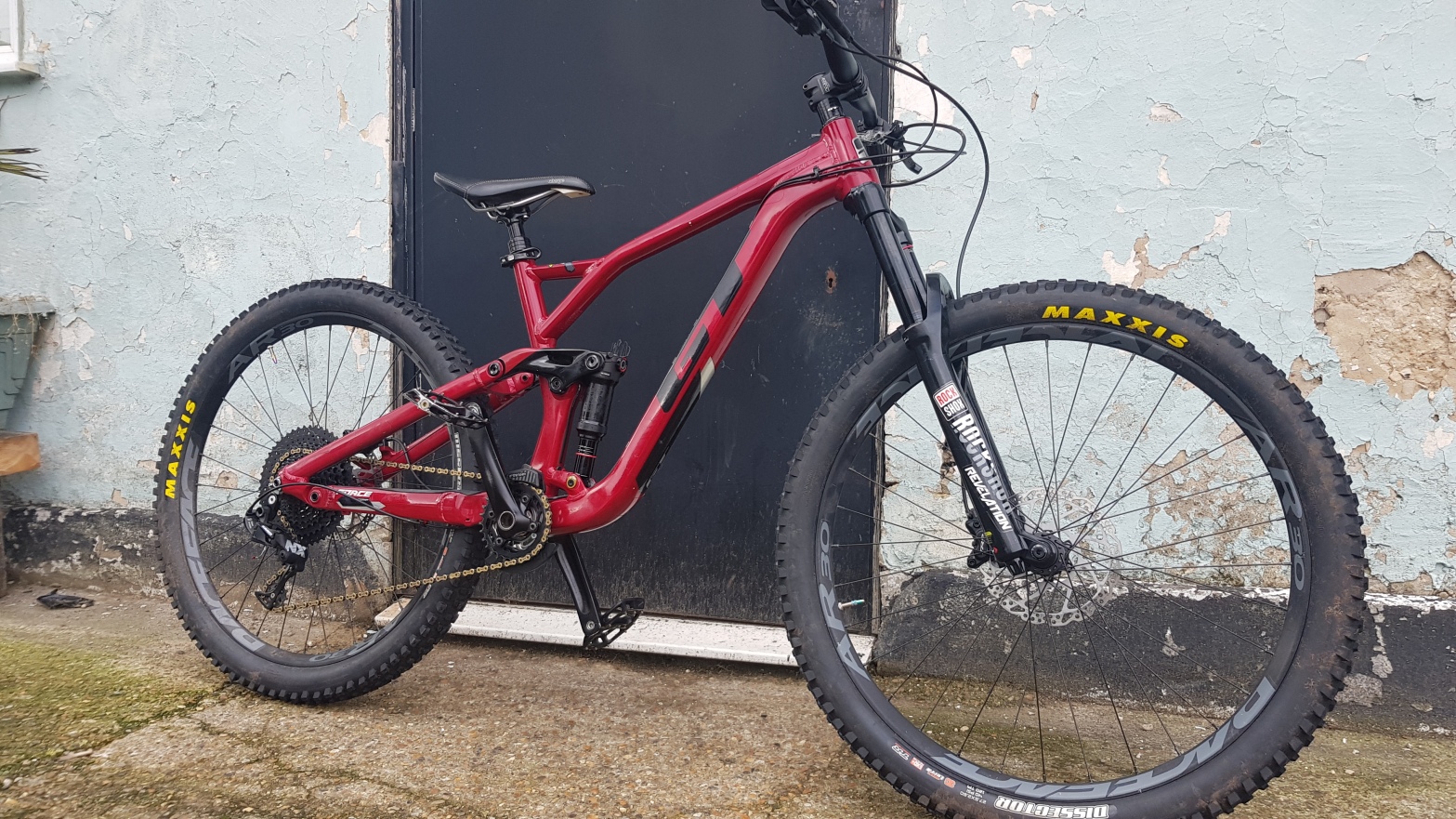
https://zeusrides.wordpress.com/2022/01/22/gt-force-comp-2019-build-part-2/

for the rough build process and mostly finished product

20210915_095751.jpg


20220122_160805.jpg
 
Back
Top