
(Posting this for reference in case someone else is trying to do the same thing...
I have an old V2.0 cycle analyst, (the small screen version) that I wanted to resurrect to use with a slightly less old Grin controller.
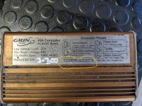
Pics of both attached.
The controller has a note on it that i need to add a diode to the CA for it to work, but it doesn't mention where to put it or what type of diode.
After a bit of reading and some guess work (no magic smoke fortunately!) I found the diode needs to be put inline on the green CA wire, which I think is throttle override. The cathode faces the CA - (the end with the stripe).
I used a 30v, 200mA schottky diode, total overkill (as the throttle signal is only 5v) but it's still tiny so fits under the heatshrink ok, cost $1 and works fine.
Without the diode, my motor would spin a bit as soon as the controller was turned on, and then the controller went into an error mode.
Hopefully this is helpful to someone else.
I later confirmed this with Robbie from Grin, who sent me this response
"There needs to be a diode on the throttle signal between the controller and the CA. The idea is that the CA can only sink current from the throttle IF the throttle is high, and some limit is being exceeded.
In terms of where to put the diode, it must go between the controller and the CA's throttle override pin (the green wire), with the diode blocking current from the CA to the controller.

So, you can cut the green wire coming out of the 6-pin plug on the CA2.0 and add the diode there, in series, such that the CA2 cannot sink current into the controller."

