
I've bought a used motor for cheap, the seller reckoned it was working fine before coming off his bike. I have some doubts and am trying to decide if it's worth working on. It is a large DD motor, I've opened the side cover and the windings look ok, but the laminations and rotor magnets appear to have seized together due to corrosion. I can only turn the axle with a wrench, and there is a grinding sound. What's the best way to clean up the corrosion to get it spinning again?
I'm currently on the road and only have limited access to tools and no Multimeter. I'll test for phase to housing resistance when I get home.
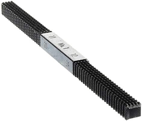
The Drive Side axle is damaged, it appears the seller tried to bash the stator out of the rotor and has damaged the axle in the process. Should I be using a die to repair this or perhaps a thread file? Should I first file the axle back to remove the "bottle neck" end?
![20220717_084238[1].jpg](https://endless-sphere.com/sphere/data/attachments/183/183209-b57a28082c660800bb1435d6b046ae06.jpg "20220717_084238[1].jpg")
The Non Drive side axle also has damaged threads. What's the best way to fix this up so I can use an axle nut again? 14mm thread die are hard to come by, most sets seem to end at M12?
![20220717_084354[1].jpg](https://endless-sphere.com/sphere/data/attachments/183/183210-33023c9d6cd089bfb2d02cf05b8e379a.jpg "20220717_084354[1].jpg")
Thanks
I'm currently on the road and only have limited access to tools and no Multimeter. I'll test for phase to housing resistance when I get home.
The Drive Side axle is damaged, it appears the seller tried to bash the stator out of the rotor and has damaged the axle in the process. Should I be using a die to repair this or perhaps a thread file? Should I first file the axle back to remove the "bottle neck" end?
The Non Drive side axle also has damaged threads. What's the best way to fix this up so I can use an axle nut again? 14mm thread die are hard to come by, most sets seem to end at M12?
Thanks


.jpg")


