Installing a CycleAnalyst 6-wire lead on xlyte 72v40a Cont

oatnet

1 MW
Joined
Apr 26, 2007
Messages
2,360
Location
SoCal, USA
Note that these instructions are unsanctiontioned and untested. This is where I think stuff should go, based on what I installed on 72/20v controllers. I could be completely wrong, so you are warned! IF YOU HAVE PHOTOS OF A PROFESSIONAL INSTALLATION PLEASE SHARE THEM!

We all love and worship the CycleAnalyst (Formerly known as the DrainBrain) sold here:

http://ebikes.ca/drainbrain.shtml

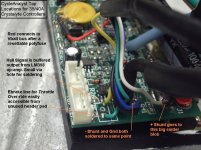
Justin (the mad genious creator of the CA) has supplied us with the picture below as an install guide for the 72v20a controller, and I've used that as a guide. I've done a handful of the 20a this is my first 40a.

http://ebikes.ca/drainbrain/Controller_%206-pin.jpg

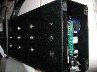
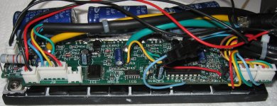
1) unscrew the 4 nuts holding each end cover plate. These heads strip easily and are tight. I recommend a VERY VERY LIGHT tap with a hammer on each head to loosen them, and then break them free by hand before using a power driver.

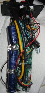
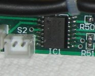
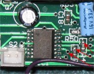
2) Note the Forward/Reverse leads are in the way of removing the PCB. WIth the 72/20a version of the controller, you have to clip those leads because they are hard wired to the PCB. On this 72/40 version, the cable is plugged into slot s2 and can be removed. Wish I'd known that before I clipped the leads, but I never use the reverse feature anyway. Anyhow, disconnect the leads in your preferred manner.

3) Remove the 12 screws securing the bottom of the heat sink to the case. Here is a picture of the 1st 3 removed.
 

Attachments

  • CA_40ah_Install_3_case.jpg
    CA_40ah_Install_3_case.jpg
    58.2 KB · Views: 1,543
4) The back of the heatsink is coated with thermal grease, have a few paper towels ready, then slide the PCB/Heatsink out of the case and onto them. You will end up with a board like below.

Note the upper left hand corner below the inlet for battery/motor power leads; most of your connections go here and we will do this first.

Note the upper right corner is a connector with a green, tangerine, and red wire on it. You will be connecting the green 'ebrake' lead to the green wire in this connector.

Note the lower right side, where the 's2' slot for the forward reverse connecter resides. Next to it is chip IC1, and I suspect the yellow wire lands somewhere off this chip. IF ANYONE CAN SUPPLY A PHOTO OF WHERE THE YELLOW WIRE LANDS IT WOULD COMPLETE THIS DOCUMENT - especially if you can verify my other settings.

Note: the picture below is pretty detailed, worth opening up if you want a closeup of the PCB.
 

Attachments

  • CA_40ah_Install_4_ Controller top.jpg
    CA_40ah_Install_4_ Controller top.jpg
    180 KB · Views: 1,560
5) Slide the new 6-lead connecter you are installing through the hole in faceplate, middle of the pack of SENSOR (not power) wires. Carefully remove the outer cover to expose extract 3-4" of color-coded leads. I stripped about 1/4" from the end of each lead. Wire-tie it to a cable bundle of your choice to keep it secure.

Carefully work the metal end plate down the wires, until it is 2-3 inches away from the controller. With the heat sink side down and the wires coming out the left, you should be facing the part of the controller you want to work on. Gently, carefully, roll the cover plate away from you, twisting the wires back to expose thies wires. Note the black lead from the battery, the read lead from the battery, and the giant solder mass connected to the negative leg of the capacitor, these are the 3 locations you will be soldering 4 of the wires to.
 

Attachments

  • CA_40ah_Install_1_before.jpg
    CA_40ah_Install_1_before.jpg
    69.7 KB · Views: 2,449
If you look at the side of the controller, you can see the (4) shunt resistors that control amps, mounted between the black battery lead and the solder mass connected to the negative leg of the capacitor. I used these as reference points...
 

Attachments

  • CA_40ah_Install_5_shunt.jpg
    CA_40ah_Install_5_shunt.jpg
    89.4 KB · Views: 1,542
My instructions from Justin for the 20a controllers was to:

a) Connect the BLACK and BLUE leads to ground. I am suprised this needs 2 ground leads, but I only understand so much...

b) Connect the WHITE lead to the other side of the shunt, which should be connect to the negative leg of the capacitor

c) Connect the RED lead to V+, the red lead coming from the battery.

If you do this, you should end up with a neater-looking version of the picture below. I had to use a globby little iron to get into the space for the blue/black, and it shows. A quick tap with my 100w iron dropped the red/white leads in place.

Note: is anyone else as disturbed as I am by the proximity of the V+ lead, and the giant solder mass that connects to the shunt resistors and V-? Is there something I can squirt into here as filler? to keep them isolated?
 
Next, pull the plug with the green e-brake wire and connect to the lead to it. I THINK the green lead on the very rightmost connecter in the picture below is the correct one. That is the one I chose and I'll confirm with Justin. I do a bad job of the pin removal and subsequent repair, every single time, so no pictures sorry. :oops:

If anyone has photos of a professionally installed controller, please post!


Note: the picture below is pretty detailed, worth opening up if you want a closeup of the PCB.
 

Attachments

  • CA_40ah_Install_7_green.jpg
    CA_40ah_Install_7_green.jpg
    279.8 KB · Views: 1,558
Finally, install the yellow hall wire - the issue of a subsequent post. I have no idea where it goes, but I think this is the correct chip and Justin mantioned something about about a handy drop on the PCB...

-JD
 

Attachments

  • CA_40ah_Install_6_chip.jpg
    CA_40ah_Install_6_chip.jpg
    18.2 KB · Views: 2,432
According to the datasheet, pins 11,12,13,14,15,and 16 are all outputs from the chip. Since the CA is only using the hall signal for detecting the motor speed, I don't think it will matter which one you hook up to.

I would try whichever one looks easiest to solder to.

Here are my suggested spots:
 

Attachments

  • commutator chip hall outputs.jpg
    commutator chip hall outputs.jpg
    57 KB · Views: 2,384
loooool,

how do think i feel?
total controller virgin!!!
hehehe


D
 
fechter said:
According to the datasheet, pins 11,12,13,14,15,and 16 are all outputs from the chip. Since the CA is only using the hall signal for detecting the motor speed, I don't think it will matter which one you hook up to.

I would try whichever one looks easiest to solder to.

Here are my suggested spots:

Thanks Fetcher!

Guess that means I am at the correct chip - I am going to give the hole at your bottomost arrow a shot.

-JD
 
knightmb said:
Very nice! Kakashi Sensi would be proud! :D

"Believe It!" :D :D :D

I was most pleased to see the scene I grabbed my Avatar from featured in the recent 'Hundo' trailer - I get to see it every day as I clear it off my Tivo. Nowadays my wife and I call the charge on our ebikes 'chakra' - and I'm a chakra-holic.

-JD
 
Hi guys and appologies for not getting a posting up here sooner. Here is a photo showing the actual tap point locations for the CycleAnalyst connector that we worked out with Crystalyte.

The only significant difference here is that the hall signal is picked up after it gets buffered through an op-amp. This prevents something going awry in the CycleAnalyst from damaging crucial circuit components inside the controller, as well as electrical noise pickup from the long cable from causing glitches in the controller output.

If you do solder the hall signal pickup into an active circuit location, I recommend using like a 5 or 10K resistor in series right where you tap into the board.

Justin
 

Attachments

  • CA taps in 35A controller.jpg
    CA taps in 35A controller.jpg
    104.9 KB · Views: 1,651
Back
Top