Currie / Tongxin Geared Hub repair

amberwolf

Administrator
Staff member
Joined
Aug 17, 2009
Messages
40,824
Location
Phoenix, AZ, USA, Earth, Sol, Local Bubble, Orion
file.php


The broken Tongxin/Currie geared hub arrived from Drewjet today;
http://www.endless-sphere.com/forums/viewtopic.php?f=9&t=25089&start=0
(quoted after my part of this post so it doesn't vanish after the marketplace thread expires).
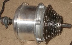
DSC03976.JPG
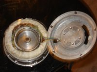
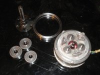
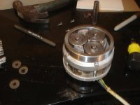
First step was disassembly to see what might be wrong (problem with the planetary and/or halls was reported) and for curiosity, of course.
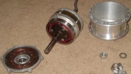
DSC03978.JPG
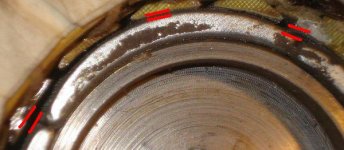
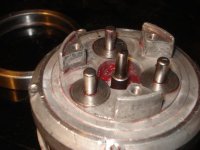
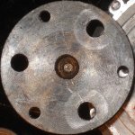
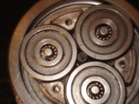
These don't have a normal planetary gear set, but rather planetary friction rollers, made of steel. Presumably they have an interference fit to start with, and as these wear they become too loose to properly transmit power under typical load, but still work normally under no or lesser loads.
View attachment 5
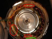
It is an interesting design, as it makes the motor itself an inrunner, with the stator outside and thus easier to cool compared to the probably more typical outrunner design I've seen on the Fusins, for example. I don't know how it affects torque, given that the magnets/rotor will be a smaller diameter, being inside the stator windings.

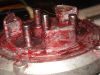
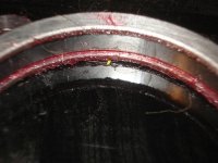
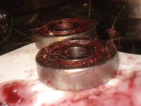
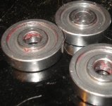
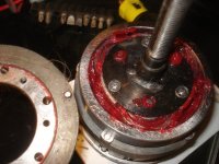
The bearings for the planetary rollers are just loose roller (pin) bearings, which don't fit tightly at all within the space between the rollers and the axles they ride on. They would just fall out when the retaining cap is off if it werent' for the thick red grease used liberally everywhere inside the planetary and clutch area.
View attachment 4
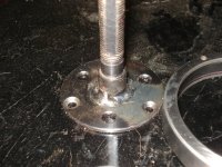
The retaining cap has a thin stainless washer covering them to keep them inside. The rollers and bearings appear to be stainless as well, but I'm not sure, as they do respond to magnetic tools. The retaining cap is welded to the drive-side axle stub, which is separate from the leftside axle, that presumably ends at the left outer edge of the motor's stator case the same way.

I'm not sure what effect this discontinous axle has on the total system strength, regarding heavy loads placed on the wheel. For my purposes with this specific motor it's irrelevant, but for a heavy cargo bike using this as a hub motor in a rear wheel, I wonder what problems it might cause, if any.


The one-way clutch appears to be a roller type as well, though I can't open it up to see for sure; I can see the springs that push the rollers or pawls outward, but not the rollers/pawls themselves.
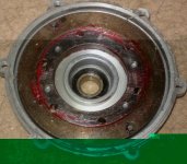
DSC03980.JPG
It's outer ring engages to the planetary's "ring gear" ring via just two little pins on the clutch (hard to see in the pics) with holes in the ring.
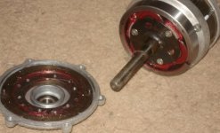
DSC03979.JPG
The inner ring engages the hub casing via six screws from outside.
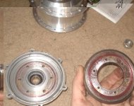
DSC03983.JPG
The side cover engages the rest of the hub cover via six more screws, on the drive side like the clutch.
View attachment 2

Freewheel threads are aluminum, part of the side cover itself. Bearing is just about centered within the threaded area, held in with a lip on the inside and a C-clip on the outside. It appears possible for the threads to separate from the rest of the casing if enough torque was applied via chain drive, but no sign of it happening on this motor is visible.
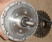
DSC03977.JPG

There is just enough of a nub on the left side that it could probably be threaded for a disc-mount for brakes, assuming there'd be clearance for the calipers to the spokes. Being aluminum, it might be possible to thread it without a die, using a steel freewheel core with cuts thru the threads for thread scrap to pass thru during cutting.

Alternately, one could be mounted directly to the cover itself, if it was drilled out in the appropriate pattern and spacers used, but the cover is pretty thin there so I'm not sure how well it would work.


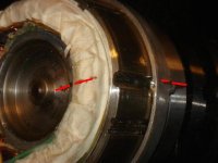
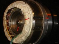
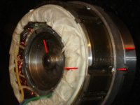
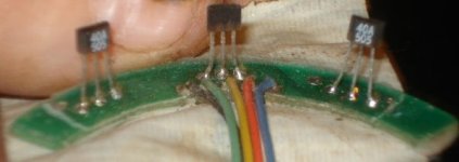
Halls are mounted to a little board on the back of the stator case, with just some paper masking tape covering them (presumably to prevent shorting by any metal bits that might migrate around the hub for whatever reason).
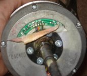
DSC03985.JPG
Phase wires appear to be 16G, either PTFE or similar teflon coated. Halls are much smaller, 24G maybe 22G, same type of insulation. Feed thru axle appears standard, as does axle size.

The freewheel cassette that came on the motor is damaged, appears that it's lockring is split right at one of the pinholes for removing it.
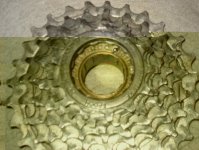
DSC03988.JPG
It doesn't freewheel, possibly because the lockring is sticking to something inside or maybe the lockring broke because of whatever failed inside. Haven't tried to open it up to find out; it's a cheapie Chinese type AFAICT, 13T-28T 7speed. I probably have parts to fix it if I find need or use for it, from other junk cassettes.


Testing with the hub opened up and motor held in my hand, leaving just the planetary spinning, the motor appears to work normally, though it sounds kinda rough (cogging?) at low speeds and just noisy at high speeds (due to the planetary I think), with my Lyen 6FET with this combo:
[pre]Motor Controller
Phase
B G
Y Y
G B
Hall
B G
Y B
G Y[/pre]
I didn't go thru the whole 36-combo chart, just stopped at the first combo that worked, as it only draws about 1.5A at full throttle, no load, on 48V (Vpower pack). So there may be other combos that work or work better.

I reassembled the hub so I could stick it in some dropouts and test with a "glove load", using some leather work gloves to grip the hub casing as it spins to load it down and see if I could cause slippage of the planetary. Unfortunately I was interrupted by the dogs at this point, and then hunger, so I will go back to do this part later, as soon as I have time. (I kinda took time I meant to spend on yardwork today to do this already).


Eventually, assuming I can find and fix whatever planetary problem there is, I'd like to try this as a middrive unit in something. It's even smaller than the Fusins, and with the inrunner design should be easier to cool with a little ventilation. Plus since it's a rear hub, I can use it to pass the power from pedals back to the wheel as well as motor power, without back-driving the pedals. If mounted in the rear dropouts of the front frame of a long bike (like CrazyBike2 is, and like it's descendant probably will be here: http://endless-sphere.com/forums/viewtopic.php?f=3&t=16920&start=0 )
then I can even use a rear derailer to shift gears for the pedals to have different gearing than the motor has, depending on conditions/etc.

Then run the chain from the motor itself back to a second regular bike drivetrain, also shiftable, for more optimal use of it's small power.


********************************************
drewjet said:
I have 3 Currie hub motors. I believe they are Tongxin, One of them I know for sure, as it is embossed on it. All 3 have issues with the gear reduction. I believe there is a fix for it. Also halls may not be working. I believe they will run sensorless, and I will double check prior to shipping. All you have to pay is for shipping. No Warranty ont these.

PM me or drewjet@cfl.rr.com

View attachment 2011-02-08 16.10.12.jpg

View attachment 2011-02-08 16.10.23.jpg

View attachment 12

View attachment 2011-02-08 16.10.44.jpg
 
flip_normal said:
There may be some useful info in
this thread about a similar toothless planetary gear hub motor called a TARN.
That is indeed useful, especially this:
nemo said:
fechter said:
The toothless planetary gear is interesting. Any idea how force is maintained on the rollers? What happens when the metal wears down a bit?
From what I saw inside:
I think that the force is maintained on rollers by clever mechanical design when the motor spindle(shaft?) in the middle is one firm point, 3 wheels can shift a little bit and engage themselves against barrel on the outside , again a firm point.
It's done by using needle bearing inside the 3 wheels with not enough needles.(img7973) so the wheels doesn't stay centered.
Because in my observations as it was running, that is what I thought I saw (slight wiggling each time I throttled it up), and there indeed are not enough needle bearings to fill the gap, only 11, when about 11.8 of them would be needed (really, 12 slightly smaller diameter ones).

So now, knowing that that is probably not wear (which I thought it was while observing it) but rather just how it works, I have to start considering other possibilities for why the rollers may not be transferring power under load (presuming that is the problem with this one, as the halls definitely are working well enough to run the motor off the Lyen 6FET).

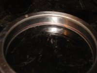
One problem reported with these according to Drewjet is that the roller system can crack; I presume this would be the outer ring rather than the rollers themselves, as it seems the rollers would have loading in opposite directions enough to prevent such a thing, while the ring is only loaded outward from the rollers against it's inner circumference. Plus the ring also has loading at two weak points (the drill holes for the clutch engage pins), where I suppose a split could occur more easily. I'll have to examine it carefully for cracking, I guess.


FWIW, that TARN motor is almost exactly identical to this Tongxin motor, with very few exceptions. The right casing cover does not have exactly the same positions for the screws holding it to the main casing, and the clutch engage pins are reversed (and a different style). It uses 12 smaller needle bearings per roller, vs the Tongxin's 11 larger ones. Green grease vs red. Looks like the TARN motor uses PVC insulated wire, rather than PTFE/teflon. Tarn uses machined-as-one-piece axle and end plates, whereas the Tongxin uses axles welded to the end plates. Clutch mechanisms are at least outwardly different.
 
AW, glad you got it so quick, and also good to see you tearing it appart. I hope you get it working, and will enjoy another of your crazy builds.
 
amberwolf said:
One problem reported with these according to Drewjet is that the roller system can crack; I presume this would be the outer ring rather than the rollers themselves, as it seems the rollers would have loading in opposite directions enough to prevent such a thing, while the ring is only loaded outward from the rollers against it's inner circumference. Plus the ring also has loading at two weak points (the drill holes for the clutch engage pins), where I suppose a split could occur more easily. I'll have to examine it carefully for cracking, I guess.

Outer ring cracking has been a fairly common failure mode with these motors, with several reported so far in the UK as having failed this way. Failures seem to be more common when these motors are fitted to larger diameter wheels; presumably due to the higher torque loading. There's a good picture of the classic outer ring failure here: http://www.pedelecs.co.uk/forum/electric-bicycles/7610-there-tongxin-expert-house.html

BTW, I think that the roller design might be cleverer than it looks at first sight, as I think that the rollers are forced outwards against the outer ring as the applied torque increases, which increases the amount of torque they can deliver without slipping (but also increases the outward force on the ring). I think that the roller bearing design is such as to allow a very small amount of outward movement by the rollers. I may be wrong though, so anything you've found here that supports or contradicts this would be useful.

Jeremy
 
Hmmm, that's true, I hadn't thought of that........ I wonder why it is that the ring cracking seems to be more prevalent on larger wheel bikes?

I remain slightly amazed at the machining tolerances needed in these motors to make them work. The fit of the shaft, rollers and ring must be pretty darn tight to make the things work - even a thou out would probably make the difference between the motor working or slipping. Maybe they have built-in some elasticity to the rollers, so they distort enough to take up the tolerances.

Jeremy
 
It looks as if I may have been right the first time. I've been reading the linked old thread about the TARN motor and found this post: http://endless-sphere.com/forums/viewtopic.php?f=4&t=435&hilit=tarn+cruise&start=15#p26472 It describes exactly how I thought the system might work, with enough play in the roller bearings to allow them to "climb" up on the spindle and outer ring.

Jeremy
 
I may be about to use this motor on my Nishiki road bike, as a BB drive:
http://www.endless-sphere.com/forums/viewtopic.php?p=511519#p511519
it'll be minus the outer shell and axles, most likely, if I do. Will likely be a while before I get far enough to know, as I have to make some parts to do it.
 
to stop ring cracking, you can make up an extra ring ( lathe necessary) theres room to slip the extra ring around the original, need to get nice tight fit,
have to heat ring and let it cool into place
 
tried to fire this up on ecrazyman 12fet but no go in any combo. put on lyen 6fet w/ comob last used andf biongo.

but i forgot the on;y retainer for begings is axle encap so the planetay shimmied upo the shaft and bearing slid under yhem. had to tale whole planetary off.

can now confirm sun, planets and ring are interference fit. now have planets and moyor (sun) in freezer yto shrink them, and will warm up ring ti expand it then try yto puyt back yogether.


while i had apart i cleaned doghair-filled grease oiut of everythign and will refill w same red grease byut new.


pics below for reference.

DSC05672.JPG


experimebnt showinbg ~12.6:1 planetary redustion. theres 4 magnets, but it cogs at 3 points instead of 4. every click of rotor moves planetary ring a bit. takes a bit more than 12 sets of 3 clicks to make the ring rotate once.
DSC05673.JPG

DSC05674.JPG

DSC05675.JPG

View attachment 18


magnets probably cog so hard cuz they are ovoid in crosssectrion not round.
DSC05678.JPG


wired in wye. phase in red and wye termination at greewn.
DSC05680.JPG


left side cover inside
View attachment 15


hall boared
DSC05682.JPG

DSC05683.JPG


contaminated graease
View attachment 12
DSC05688.JPG
DSC05687.JPG
DSC05689.JPG


green arrow shows whewre bearinsg fell into mostly
View attachment 11


all clean
DSC05691.JPG
DSC05692.JPG
DSC05693.JPG
DSC05694.JPG
DSC05695.JPG
DSC05698.JPG

plate paert of axle end i need to duplicate
View attachment 2
DSC05697.JPG


.
 
seems to have worked ok, though getting parts together fast enuough took a couple triews with just one hand. frozen metal is COLD. :lol:
DSC05712.JPG


i fit planets in ring, then placed over mot shaft. tilted planets down at center edge wherte conyact mot shafrt, w shaft centered right on edges, then tapped w hammer lightly till they engaged shaft.

set axle/retainer plate over them then pressed till they levelled out. used long screws to get plate/planets down to point actual shrter screws woul reach and swapped screws.

tightened those down till plate flush w/ motor case. pulled plate off then insetred bearings till i ran out of room; had to wait for it to warm up to get rest in.
DSC05713.JPG
now i just need to dupe the axle plate that retains bearings w/ a extension to hold a bearing od slipo ring to hold cliutch on, drill or file sprocketto mount on clutch, and fab mount for motor on nishiki.
 
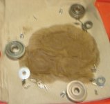
oh forgot to mention that i think 2 bearings are somehowmissing. :? i only have 11 for 2 of the planets and 12 for 3rd. for now i didnt put 12th in at all.

motor runs, need to grease it up and do rpm tests while i still have the tachometre,. should make calculating gearing ratios easier.
 
greased up but something's wrong; it makes a bundle of noise an gets warm just running for a few seconds at a time over several minutes. now has >3a no load curreent with same pase/hall combo that used to have half that.

probably the 3 needle bearings that are missing? it only has those and a mid-shaft bearing for the rotor core shaft toi keep rotor lined up.

video of noise (paper bit on ring is for rpm tach sensor yo read in later test)
[youtube]01E_l7lOAKQ[/youtube]


rpm is 328 max on 38.2v rc lipo 10s. min rpm is 17.3-ish.
 
Just adding a link here to anyone looking for info =on the Tarn version of this motor.

Slight differences and info on how to remove the rotor if you need to get it out to re stick the magnets...DON'T TRY PRESSING IT OUT FROM THE 'GEAR' SIDE

http://endless-sphere.com/forums/viewtopic.php?f=3&t=42814&p=627718#p627718

Other difference is that you have to take the side plate off to get to the halls. and then fit very tight into some brittle clips near the coils. Hall board looks the same though
 
Sorry for waking up an old thread (I especially registered to ask this question). What kind of grease is needed for this roller friction planetary system? I have a bike with middle motor myself, but all the grease has been getting hard, so need to replace it, what is the grease to use?

Hoping for a reply.

Cheers
 
I'd probably go for whatever you had to hand, a basic gear or wheel bearing grease should do just fine
 
Hello NeilP,

I have put in grease that is from the brand Unil (Belgium) and the product line Synplex, suitable for mowing heads and outboard engines (the ones at the back of speedboats and such). Excuse me for Google translating these few words and any errors it produces. Because I read that you need a high viscous grease to prevent the oil film from getting separated. I did tested it on a run before reassembling the engine back on the chassis and the rollers got just beyond handwarm (don't know whether they are normally need to stay cool?). The grease I have put in sort of has the same viscosity as standard wheel bearing grease.

Thank you so far for your reply! Much appreciated!

Cheers
 
Thanks for the quick replies :)

Don't know if it is for gears, doesn't state it isn't or is either :/

Anyways, thanks for your help. I'll try to inform somewhere else too and if I get a different answer or some specific grease that needs to be used I'll let you know how it works out.

Again, thank you so much for your quick replies. It helped me further in the 'investigation'.

Cheers
 
Back
Top