tell us about your regen braking setup

monster

100 kW
Joined
Jun 17, 2007
Messages
1,411
hi

this is a post to discuss the nity-gritty of regen braking. who has it, what kind have they got and how is it implemented. i have braking only regen braking where the motor coils are shorted out during braking by use of a relay. this is too powerful for my dropouts so i treat it as an emergency brake.

im interested in those that have use light bulbs for different braking potentials. whats your experience?
 
We have discussed regen braking several different places. I'm not very happy with my system either, although it serves my primary reason for installing it very well. I currently coast down the hill from my house to the local village at about 13 - 14 MPH with very light additional braking. The grade varies from about 10 to 20 degrees. The system consists of toggled relays that connect each motor to three 130 Watt light bulbs.

The main problem is that the system uses 12V light bulbs which will probably blow if I exceed 14 MPH while using them for braking.

I have looked for simple solutions to this problem and have been unable to find one. Now that I have a trike with good brakes I am thinking of going to 2S2P on the bulbs for 24V 520 Watt which would allow the regen brake to be used up to about 28 MPH. The problem is they would not be as effective at lower speeds.

I would also like to automate the system so that the regen brakes come on when the trike brakes are used. Since I can't simply replace the brake levers (the front lever has a built in parking brake and the rear lever has two exiting cables) I might add a momentary button (like a horn botton) in series with the regen brake circuit from the toggle. If this button is located near the hand grip or such that it is closed when one of the brakes is applied it would be handier than having to switch the toggle on and off. I would still use the toggle so that powering and braking can not be done at the same time.

The ideal system would use a controller and a variable lever (throttle?) to alter the load and hence the braking force. This might be overkill, because the braking, although positive, is very smooth when applied at any speed.
 
hi. i remember we spoke about this before but i understand more about it now so i'm gonna give it another go. i want a system like yours with the light bulbs. i know that volt=speed and current=torque but how does this relate to regen braking? do higher amp bulbs slow you faster? what speed range is the braking good for?

i like my emergency brake (shorted coils) for safety, but i also want to reduce brake pad wear using your bulbs idea. i'm thinking of a double relay system with two buttons on the handle bars one for emergency and one for braking at speed. i think this will cover all the speed ranges safely 0-15mph = no bulbs, 15-40mph = 24v bulbs.

what do you think about the speed ranges? have you done any tests to see what motor speeds give you what voltages?
 
IMHO, shorting the motor leads or switching them over to a load is not regen braking but rather plug or dynamic braking.

regen braking --> energy back into batteries
plug braking --> energy into heat

When shorting the leads of the motor, the windings of the motor need to absorb all that energy. This is a good way to cook your motor! If you use an external load like a light bulb, then the bulb absorbs the energy.

If you are worried about the voltage rating of the bulbs, you could use a coil of light gage wire (say 30 feet of 16awg) or a ceramic resistor instead. The higher the resistance, the less braking.
 
Matthew asked:

have you done any tests to see what motor speeds give you what voltages?

Over a year ago I wired an automotive volt meter between a 26" front hub motor (WE BD36) and a 24V light and did a few tests. The voltage produced was directly related to the speed and by coincidence on this setup almost matched the MPH. I have not repeated these tests with my 20" wheels (same motors) but I often allow the trike to reach 14MPH during regen braking (I like to call it motor braking). So far none of the 12V bulbs have failed.

do higher amp bulbs slow you faster?

Yes. I am currently using three 130 Watt bulbs in parallel per motor. When the same bulbs are wired in series, you don't risk breaking the bulbs, but you get less braking at lower speeds.

If I could find a low cost, light weight, variable resistor that worked as good as the light bulbs I might switch. But when I first started doing this I had three hub motors on the MB and trailer, so anything I did was times three. Currently I am only using two motors on the trike/trailer so the braking force is only 2/3 as strong.
 
i think the light bulbs are limiting current the same as they do in my homemade battery charger. without bulbs, the current is free to move round the motor coils and dissipate as heat. with bulbs, the current is limited by the flow through the bulb. the current is the same through the coils and the bulb but the voltage will be different. the volts, and hence heat, dropped across the motor and the bulbs will be proportional to their resistance. but resistance changes with heat so it gets complicated. but i think that the stopping effect comes not from the light bulb but from the fact that power is being dissipated in the coils. if you measure the resistance in bulbs of different watts the higher watt bulbs have less resistance. so if higher watt bulbs stop you faster then that is because they are letting more current through to be dissipated in the motor. therefore the bulbs are just protecting the motor but at the same time they are impeding the braking power buy limiting current. motor heating is an essential part of motor braking i think. do you agree?

my crystalyte motor is cool as a cucumber all the time so im not worried. someone said that they can go up to 5K watt so i am not worried too much about it. if i had a motor that got hot during normal running like some of those MY1016's i would not try this.
 
Matthew, I think you summed it up well.

By my calculations, using 3 130W 12v bulbs in parallel is equivalent to a 0.37 ohm resistance. Using a loop of wire would do the same thing, and the resistance wouldn't change with temperature (mostly). 13' of 14awg would have about the same resistance.

I'm trying to get my head around where the losses go when you use and external resistor. I was thinking that it's simply I^2R. The current is the same in the motor windings and the resistor. But since the external resistor's resistance is greater than the motor windings that it would heat more.
 
Matthew, I may not have followed your last post, because I don't think I agree. An EE may have to set us straight here, but I believe when my brushed motor is working as a generator it will produce a fixed voltage at a fixed RPM. When a load is connected to the motor it will try to generate whatever amperage the load is designed for. So if the motor is spinning at a speed that generates 12 volts and a 12V 5 amp light bulb is connected the bulb will light up with very little effort by the motor (i.e., not much braking force). But if a 12V 30 amp light bulb is connected the motor will have to work hard to produce the 30 amps the load is designed for, thus producing a great deal of braking force. In neither case, will the motor heat up (that is what the light bulbs do). If the motor is directly shorted, it's not the heat that slows you down, but the generation of amperage. The motor heats up because that is where the current is directed.

I think your argument makes sense in your charging circuit, because you are just puting multiple loads in series and thus dividing the available voltage between them. A simple example would be to hook a 12V bulb to a 24V battery. It will blow. But hook up two 12V bulbs in series to a 24V battery and each bulb will operate on 12V and they will not blow.
 
Ted_Z said:
I'm trying to get my head around where the losses go when you use and external resistor. I was thinking that it's simply I^2R. The current is the same in the motor windings and the resistor. But since the external resistor's resistance is greater than the motor windings that it would heat more.

Correct. If the motor winding resistance is much less than the resistor, then most of the heat will go to the resistor. The split will be porportional to the resistance values. If the motor resistance equals the external resistor, then the heating would be evenly split.

At very high speeds, it would be easy to generate currents/torques that are high enough to damage something. The braking torque will be directly porportional to the current.

Some kind of switchable resistor would be best, so at high speeds you can use a higher resistance. Ideally, you'd want the current to be nearly constant over a wide speed range.

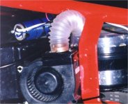
I made a braking resistor for my 24v Zappy by winding a bunch of 22 ga. wire around an aluminum tube. On a bike, you could wrap wire around a section of the frame where there is plenty of cooling. As I recall, I used about 20 feet of wire for 24v.
 

Attachments

  • ZappyBraking resistor.jpg
    ZappyBraking resistor.jpg
    46.4 KB · Views: 4,378
fechter said:
On a bike, you could wrap wire around a section of the frame where there is plenty of cooling. As I recall, I used about 20 feet of wire for 24v.

Alternatively:
In winter, make yourself a poncho from an electric blanket and stay nice and toasty.
In summer, carry an electric kettle on your rear rack so you can offer friends a nice cup of tea.
:D
 
Hmm... That's a great idea. You get colder when you're going downhill anyway. I've seen 12v electric vests for motorcycle riders. Just watch that voltage! Too much could set you on fire :shock:
 
fechter said:
Hmm... That's a great idea. You get colder when you're going downhill anyway. I've seen 12v electric vests for motorcycle riders. Just watch that voltage! Too much could set you on fire :shock:
Don't forget the heated hand grips! :p
 
Ok guys, I'm convinced (that I don't know anything!). So i'm ready to do some more experiments. Fechter, does it matter if the tube is a conducter? does the tube diameter have any significance or is it's main purpose to just keep the wire evenly wrapped to facilitate cooling and eliminate hot spots? Do you just connect the two ends of the 22 ga. wire to the + and - leads from the motor (i.e., instead of the light bulbs)? My main goal originally was to do something that would not damage the motor. My EE fishing buddy had told me I could directly short the leads from the motor, but he didn't recommend it. This simple coil of wire seems just too simple and easy. :D

Thanks.
 
As long as the wire is insulated the tube can be anything. Mine was bare aluminum.

One version overheated on a hill and started smoking, so watch it carefully the first time out.

If the wire seems to be overheating, then use a longer piece of heavier wire.

You could wind it in several sections and have a tap between sections to select different resistances with a switch if you wanted. Perhaps just a high/low setting would be enough.

Yep, just hook it up to the motor leads. This should work with both brushed and brushless motors, but with a brushless motor it would be best to use 3 sections in a 3 phase configuration.

On my Zappy, I rigged up a 15 amp microswitch to the brake arm so it would turn on the resistor when I barely touched the brake lever.
 
Thanks for the info. I will report back here in a few days after doing some tests. The weather forecast is good for the next few days. Beats last Monday when the wind exceeded 100 MPH along with heavy rain. One neighbor had both panes of a 4 1/2' by 6' window shatter and another buddy lost 1/4 of his asphalt shingles on one side.
 
whats the advantage of this over the light bulbs? doesn't it blow at higher speeds? is it good for all speed range's?
 
Backing up to my first "heavy" power trailer behind a cheap MB with terrible brakes, I had to creep down the big hill at about 5 MPH. So adding the "bulb" motor braking allowed me to go down the hill at 12 to 14 MPH with very light use of the MB brakes, plus it was easy to bring the bike to a full stop on the hill. Now that I have changed from the MB to a trike with much better brakes I am comfortable with a higher speed going down the hill, but the 12V bulbs will pop if they are over volted too much.

So I figure if a wire coil resistor can be dialed in just right to maintain a speed somewhere between 15 and 20 MPH on the hill, without using the trike brakes, and with no worry of popping light bulbs, I will be happy. Several times I have gone down hills less steep and the trike has exceeded 25 MPH. At that point I didn't dare flip on the motor brakes because the bulbs would have popped for sure, so all braking had to be done with the trike brakes. I figure with the resistor system I can flip the toggle to brakes any time I want to slow down or stop, regardless of speed. If I want to maintain a certain speed while coasting down a hill I can flip the toggle on and off as needed (this is where a micro switch on the brake lever would be nice). I have already used this technique with the bulb setup on 10% grades, and it works nicely up to my limit of 14 MPH.
 
Rassy said:
I would also like to automate the system so that the regen brakes come on when the trike brakes are used. Since I can't simply replace the brake levers (the front lever has a built in parking brake and the rear lever has two exiting cables) I might add a momentary button (like a horn botton) in series with the regen brake circuit from the toggle. If this button is located near the hand grip or such that it is closed when one of the brakes is applied it would be handier than having to switch the toggle on and off. I would still use the toggle so that powering and braking can not be done at the same time.

Have you looked at motorcycle brake levers? There is a tab on the bottom of the lever that pushes on a plunger switch to actuate the brake lights. Maybe you could modify your existing lever with a tab and use a motorcycle brake light switch behind it.
 
Just did a short test of "plug" braking (thanks Ted, I like that term, and will start using it instead of "motor" or "regen" braking).

Ted said:

you could use a coil of light gage wire (say 30 feet of 16awg)

Fechter said:

I made a braking resistor for my 24v Zappy by winding a bunch of 22 ga. wire around an aluminum tube. On a bike, you could wrap wire around a section of the frame where there is plenty of cooling. As I recall, I used about 20 feet of wire for 24v.

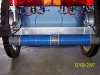
The lightest wire available in the local village was 18 ga. so I made two 30 foot long coils, one for each motor, wrapped around a piece of 1 1/2" pvc. I only had time for a short test, but the braking effect seemed less than the old bulb setup. Tomorrow I will run down the big hill. If my speed is held under 20 MPH without any mechanical braking I will probably leave them alone. However, if I want to make the braking force stronger, My understanding is that a larger gauge wire, such as 16 awg , would be required. Fechter and/or Ted, can you confirm this for me? There was no heating on the coils or the motors during the short runs today, so tomorrows test will be for heating issues also.
 
To increase the braking effect, you can also shorten the piece of wire you have. You can make multiple 'taps' along the coil with connections to vary the braking force. Ideally, you'd want to be able to do this while riding :wink: Some kind of rotary switch with a spring return would allow increasing force in steps.

If you use a shorter piece of wire, the heat will increase more than porportional to the length of wire (in other words, keep an eye on the temp). If the wire is spread apart slightly so the coils don't touch each other, the dissipation will be much more.

I used aluminum tubing so there would be some heat transfer to the metal. If the surface area of your wire is enough, then it won't be an issue.
 
Thanks fechter, I appreciate the help. I will slowly test and shorten until it "feels" right :D . I think the right setting will fit my needs, but multiple braking forces could be handy. It would take a fair amount of effort with multiple relays for the two motors on the trailer. If heating seems to be a problem I'll look for a piece of metal tubing to work as a heat sink.
 
Okay, it works great. Each coil is made from 35 ft. of 18 ga. insulated copper wire. The 35 ft. includes the several feet that goes inside the trailer to connectors. The braking force is slightly stronger than the bulbs were, so I guess that means the resistance is slightly less.

I tested the system wheels up, and both brakes were definitely working. I stopped about half way down the hill and one coil was warm but the other one was still cool. Both hub motors were cold. At the bottom of the hill the one coil was slightly warmer than the other one and both hub motors were still cold. Maybe I have a poor connection some place.

I never touched the trike brakes, except when making the full stop to check the heat. On the lower part of the hill (10% grade) I flipped the toggle on and off a few times, letting it coast over 15 MPH, and everything was real smooth. On future tests I'll let it coast to higher speeds before throwing the toggle, eventually, hopefully, finding out what it does when the brakes are engaged at speeds over 25 MPH.
 

Attachments

  • Brake Coil.jpg
    Brake Coil.jpg
    46.9 KB · Views: 3,938
How can I connect a simple resistor type brake to my brushless motor/controller without hacking it to death?

I have a Crystalyte 20amp controller, 408 motor, CycleAnalyst and A123 66-volt batteries.

Guessing there's no easy way without sacrificing the CycleAnalyst or something, at least during braking.

Richard
 
Matthew, thanks for starting this thread and letting me get into using a "resistor" instead of light bulbs. I hope my experiments gave you some fresh ideas for your own setup. At this point I definitely would recommend the wire coil resistor over light bulbs. Cheaper, easy to change the braking strength by altering ga. and/or length, and no worry about actual voltage.

rf, fechter mentioned using a coil resistor on each phase wire on a brushless motor. Way over my head. Good luck.

On my last test today I let the trike reach 20 MPH before toggleing on the plug brakes. It was smooth and worked fine.
 
Back
Top