Controller shunt mods

wesnewell

100 GW
Joined
Jan 31, 2011
Messages
7,171
Location
Wylie, TX, USA
I've got a 48V controller that draws about 30A and gets 25+mph using a GM 500W rear hub. I've ordered a cheap 72V controller to try on it, but am thinking about modding the shunts on the 48V one I have now. It has pads for 3 shunts, but only 2 are used. I want to get ~40A draw from the controller, but while I'm at it, I'd like to add a toggle to effectively limit the amps by running one of the shunts through the switch. Does this sound right?
 
You could add a shunt.. orr... add some solder and see how it goes.

shuntmod.jpg


I took a 22 amp ampedbikes/cell_man kit controller and added about 8 amps with a sizeable gob of solder.
Worth a try and a lot cheaper. Start out small and work your way up.

Variable current limit... i've heard that the resistance from the switch wire makes this a problem.. been a while since this was brought up though.
 
Hm, how many amps were you drawing at peak?

I do all my testing on a hill that is about 5 miles. Will take peak amps the entire time. If the controller can handle that without getting so hot you can't leave your hand on it, it can handle anything ( of course a dead stall like you mentioned is another problem in itself )
 
I also added an 18 ga. copper wire to my 22 amp ebikekit controller. It peaks at 55 amps now :twisted: It does drop back to 35 amps really fast and quickly drops lower yet as I accelerate. Not many runs on it yet so the jury is still out on longevity..
 
55amps on a 6-9 FET? Stay away from hills at all expense :lol:
 
neptronix said:
55amps on a 6-9 FET? Stay away from hills at all expense :lol:

Lucky I live in Kansas :mrgreen: Also it is used with a 9C 6x10 hub in a 20 inch rim. I really have to try hard to hit 55 amps. Usually when the front wheel is off the ground at startup :mrgreen:
 
wesnewell said:
I've got a 48V controller that draws about 30A and gets 25+mph using a GM 500W rear hub. I've ordered a cheap 72V controller to try on it, but am thinking about modding the shunts on the 48V one I have now. It has pads for 3 shunts, but only 2 are used. I want to get ~40A draw from the controller, but while I'm at it, I'd like to add a toggle to effectively limit the amps by running one of the shunts through the switch. Does this sound right?
As long as the switch is low-resistance, too, then it should work, but it's possible for a switch to be higher resistance than a shunt, so it won't end up the total resistance you expect.

Also, it will increase as the switch gets hotter from current passing thru it; remember that in theory, assuming the shunts were all equal value, the switched one would see 1/3 of your total battery current flowing thru it at any instant. Since the switch will add some resistance, possibly double it, it may only see 1/4 or less, but that's still a lot at high loads. ;)


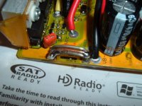
How many FETs does your 48V controller have, and what kind are they? I'd guess it's a 12FET for 30A (assuming constant), as that seems about right for both of the 12FETs I have here. 40A is a third more than original, whcih is a lot. My 12FETs will allow up to 60A momentarily, but not for long (a second or two?), just as I start from a stop. Haven't tested it on a steep hill yet, under high throttle (I try to avoid those).

Too few FETs with too low a rating could end up blowing some, running at 40A continous; I'm not sure what rating you need for this, as it depends on the phase currents they see (very different from the battery currents, which is what the shunt measures).
 
auraslip said:
It wasn't blowing 40 amp fuses, but it was blowing 30 amp fuses.

I'm curious on how you modded your control torker - any pics or threads?

Yea no guarantees though ! :mrgreen:
 

Attachments

  • Infinion shunt mod.JPG
    Infinion shunt mod.JPG
    47.9 KB · Views: 19,877
Finally got around to modding the shunts. Took the quick route and just wrapped some 26 gauge bare tinned wire around both the shunts on one left side and then soldered it up. I added approx. 1/3rd of an inch. Quick test run and it maxed out at 41A from about a 2mph start going wot. Suspect it might go a little higher from a dead stop, but no more than 45A. I'm going to forget the switch setup as that doesn't look promising with the little toggle switches I have on hand. Pictures of the controller before the mod are here if anyones interested.

http://endless-sphere.com/forums/viewtopic.php?f=2&t=28078
 
jonathanm said:
How does the motor handle it? are you seeing any significant gains? temperatures?
Assume the motor handles it fine, although I didn't check the temp, and never have. It only stays at 40+ amps for a few seconds, then starts falling back pretty quick. About all I noticed was it gets up to speed faster. Haven't tried any hills yet, but I'll give them a try later today. There's some pretty good ones going down towards the lake.
 
Cool....look forward to hearing a more detailed report. when you say getting up to speed faster, are you seeing more torque from a standstill (ie stop lights) or is the extra grunt coming once the motor gets moving a bit? temperature wise - even if you can just have a feel with your fingers and see if it gets much hotter than before would be handy to know. Thanks Wes :)
 
Just went for a 4 mile ride down to the lake and back up the hills. Didn't check motor temp before leaving, but I could leave my hand on it when I got back. It was hot, but don't know how much of that was due to the 100F temp outside already and probably 120F leaving the garage. Never went over 32A climbing the hills and it got up to 20mph going up them. I don't think there's a thing to worry about. Works for me. Should have the 72V controller in a couple of weeks. Time to order some more lipo.
 
I got the motor to 146F the other day going to work with a strong headwind. And yesterday the motor was at 126F with the wind in my back, maxing out at 41mph. The Ebay motor doing better than I thought it would.
 
Correct, I'm using Lyen sensorless controller and the controller peaks at 39A. Average is below 20A.
 
newbiehere said:
If I may ask, how do these two solder pieces limit or increase current limits?

The controller monitors its current draw with a shunt. A low resistance piece of wire, it reads the voltage on the wire and from that extrapolates the current draw. Ohm's law and all that.

If we solder the shunt, we lower it's resistance, allowing it to pass more current for a given voltage drop. In effect tricking the controller into thinking it's still drawing it's normal current limit, but it's really drawing more current.
 
thank you for your reply. So there is a dedicated chip to monitor the current? I cant see any traces on my controller to a chip, only the shunt from the black power wire to source lead of a Mosfet.

Are you saying that any modification to the shunt, like a small amount of extra solder, will change the amp monitoring reading?
 
newbiehere said:
thank you for your reply. So there is a dedicated chip to monitor the current? I cant see any traces on my controller to a chip, only the shunt from the black power wire to source lead of a Mosfet.

Are you saying that any modification to the shunt, like a small amount of extra solder, will change the amp monitoring reading?

The controller will still think it is drawing its normal amps, but in reality it will not. So your controller display or app will have a bad reading for watts/amps, if it has one. The bms-s app would reflect the correct value. If your throttle has a voltage display, it will also reflect a larger voltage drop because of the increased draw.
 
yes but Im asking how does the shunt work? Is it the same principle as a current meter that uses a shunt? what part of the controller senses the current, or what is the shunt connected to?
 
The voltage across the shunt is measured by the MCU. Many times it first gets amplified by an op-amp. There has to be a trace from the shunt to a chip somewhere. It might be a really skinny trace.
 
Back
Top