Are these schematic drawings correct?

raulen

1 mW
Joined
Nov 14, 2007
Messages
10
Hi there, I have 120 sub-C cells to build a 48V battery, but this is going to be my first e-bike project and I´m not precisely an expert at electrical stuff.

These are the specs of the cells:
-Type: Sub-C
-Chemistry: Nimh
-Voltage: 1.2V
-Capacity: 4500mAh
-Standard Charge: 15 hours @ 300mA
-Rapid Charge: 2 hours @ 3000mA
-Weight: 57g
-Dimension: Height: 43mm / Diameter: 23mm
-Tabs: Yes

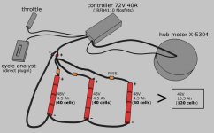
They are Tenergy cells (red color) with a rated short-time current up to 40A. I plan to build 3 bateries (48V 4.5Ah each one), then I´ll connect them in parallel to get 48V 13.5Ah, with a short-time current up to 120A. This is to be used with a X-5304 motor and a 72V 40A controller.

Should I connect a fuse to these batteries? 40A fuse? And how do I connect it, maybe between the positive poles of every 48V battery?

I made the following drawing to illustrate the connections:
01qd4.jpg


To recharge the batteries I´ll use 3 different chargers in this way:
02bch5.jpg

These are the chargers:
http://www.powerstream.com/nimh-3pn9.htm

Are these schematic drawings correct?

Thanks.
 
I'd suggest using a separate fuse for each string. This will protect against more possible shorts. If the controller limit is 40a, then each fuse would only need to carry on third the total current. You want some 'headroom' in the fuse rating, but I would think 25 - 30 amps would be plenty for each string.

Keep the fuses in the circuit for charging too. The fuse should be physically close to the end of the string to minimize the chances of an unprotected short.
 

Attachments

  • Parallel string Ni setup.jpg
    Parallel string Ni setup.jpg
    34.7 KB · Views: 1,729
I agree with Fechter's input. I would keep the fuses smaller and close to the indivicual packs.

conceptual stuff:

How do you isolate the packs during recharge time?
If not diode isolated then maybe a pull out DC power plug that isolates for charging? Break the circuit after the indivicual fuses, between the fuses and the load- controler. charge thru the individual fuse to each battery and that reduces wiring.

I like high curernt multi contact plugs versus switches.
 
My idea is to use pull out plugs, yes:

01xl1.jpg


02qf3.jpg


I think I´ll use standard car fuses and waterproof fuse holders, is it ok?
About the plugs/connectors, I was thinking in Anderson Powerpoles (PP-45 or PP-75). What do you think?

I like high curernt multi contact plugs versus switches.
I´m not sure what that is exactly, and I found very different results after looking for it at google. Do you have a picture or something?
 
"I like high current multi contact plugs versus switches."

I´m not sure what that is exactly, and I found very different results after looking for it at google. Do you have a picture or something?


It is a just a term i use.

you can configure three Anderson power poles (30 amp should be fine) to connect the hot side of the pack to the load- three more andersons of course.

then disconnect the packs from the load to recharge. then you connect the pack's anderson plus connector to the three charger 'plus' lead, which now have anderson connectors. ground and thermistor contacts can be almost any 'polarized' connector.

After getting everything right electrically, you can mate the charger anderson housings together, like wise for the pack andersons,. and the load andersons. makes the manual part of changing from charging back to riding a litle easier.
dick

Yeah, good idea. I´ll try that.

Just one more question: what wire gauge should I use? 9 AWG?
 
10 gauge has 1 ohm per thousand foot, 12 gauge 1.6 ohm.

http://www.powerstream.com/Wire_Size.htm

so for a 10 foot wire, worst case round trip, 12 gauge would be .016 ohms. if your PEAK current draw was 50 amps, that would still be less than 1 volt dropped due to wire size, could even go 14 gauge (2.5 ohms per 1k ft) if the runs are short.

check with the wire gauge accomodated by the anderson power pole contacts- they have limits.

If you have to buy the wire, try for the high flexibility stuff, lots of small strands. It bends and follows the bike tubing better than the really stiff stuff.

dick
 
Yeah they recommend 10guage for 45a anderson connector. 12gauge for 30. You might need larger connector for bigger wire. I had problems crimping 2 12guages wires to one 45a connector.
 
According to the chart I can safely use 14 G wire on most of my connections for my Bent" bike under 12 feet long. Thats amazing, but for safety I'll go 12G except for the charging lines and other very short runs. That makes thing easier to use and a bit lighter. Thanks "Deardancer" for clearing that up.
 
Generally the losses in the wiring will become unacceptable way before they get to the burning up point. You can run 30 amps through a 14ga. wire without frying it, but if the wire is long, the voltage drop will really eat into your efficiency. The longer the wire, the more important the losses are. Also, the wires that go between the motor and controller have to handle higher current than the battery wires, so they need to be heavier / shorter.

On a stock Vego scooter, I measured the voltage drop on the wiring at a typical riding current. The losses in the wire were over 10% of the total power. Just by using slightly larger wire, the losses were cut to around 2%. This equates to better speed or range.
 
fechter said:
Generally the losses in the wiring will become unacceptable way before they get to the burning up point. You can run 30 amps through a 14ga. wire without frying it, but if the wire is long, the voltage drop will really eat into your efficiency. The longer the wire, the more important the losses are. Also, the wires that go between the motor and controller have to handle higher current than the battery wires, so they need to be heavier / shorter.
quote]

Highly agree with Fechter here.

Another thing to consider is the really big peak peak momentary current.
Few of us mortals will really know how big a current spike the motor or control will try to extract from the system for 1/10 second, and few would ever try for a really quality A/B comparison of acceleration by changing only the gauge of wire.

The famous brushed controller company, 4QD, told me to count on 4 time the rated continous maximum rated output of the system for Peak instantaneous power needs. So if I had a 400 watt motor at 24 volts, put wiring in that wil drop less than 5% power at that peak. so that would be a 1600w peak peak, and 67 amp peak.

So at 24volts, had to use 10 gauge for the long run, just to keep from sacrificing some extreme case acceleration needs. And when one is wiring a 24v system on a long wheelbase recumbent with a handlebar 'full current carrying meter', this stuff starts to become apparent.

(This is one reason you are better off at 48 volts; wire and connectors are not quite so critical)

Anyway, these extra gauge calculations are not the kindof stuff concerning wires overheating, or normal flat land moderate speed loss of efficiency. Its about the extremes of performance on tough sudden hill climbs or acceleration.

If the maximum wire gauge for your contacts and connectors say 12 gauge, use 12 ga., keep the wiring runs moderately short, and buy the high flexibility wire . No money at all compared to the time spent trouble shooting trying to figure out why your acceleration is a little below expectations- you will KNOW its NOT the wire gauges.

Then comes the quality of the crimps, connections, soldering, etc. The quality of that work, or lack of on just one heavy current joint, will negate all the other stuff. (one junction at 0.1 ohm, 30 amps will drop 3 volts by itself)

There are a few customers I have seen that want "the clean look" no matter what, and are not that concerned with that last bit of hill climbing power. Hopefully they dont weigh as much as some 250 lb riders with"bigger" needs.

good luck

dick
 
:| Back to the original plan of using mostly 12G wires, I kinda wanted to stay away from 45 amp Andersons if possible, I'm using "high discharge, Lifebatt" batteries on a long ( 7 feet) bike.
I would never purchase a "Watts-up" meter for the sole reason of the wire issue, "cycle analyst" only, pay to play.
Thanks for bringing me back to reality guys, bit of a kill-joy, but 12-10 gauge it will be. :|
 
:arrow: Deafscooter here and ( Craig Watch what you doing hook up the battery packs )
=====
====
===
==
=
Craig Uyeda
Deafscooter
 
Back
Top