Phase cable upgrade with magnet wire

auraslip

10 MW
Joined
Mar 5, 2010
Messages
3,535
For those who have, or tried, to upgrade the phase cables in our DD hubs to 12awg understands the frustration of trying to cram them and the halls + temp sensor wires down the axle.

John in CR has done it with magnet wire instead, and it seems like an easier way.

Re: 9c phase wire replacement...help

Postby John in CR » Wed Dec 01, 2010 8:00 pm
"...while pulling the 3rd phase wire through"...There's your problem. The entire wiring harness needs to go through at once, and it should be enclosed in a protective sheath.

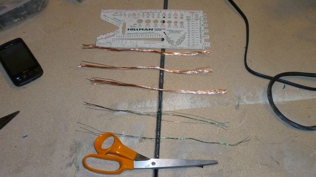
I finally got around to mine today. I used magnet wire, 17 strands of 24ga per phase, so a bit larger than 12ga. I also included an extra pair for adding a temp sensor later. I only twisted only the ends together of each 17 strand group, so the phases are separated at the ends. Then I wrapped the entire bundle of 53 strands of magnet wire plus the 5 hall sensor wires in a single layer of electrical tape, and covered that in shrink wrap. I didn't have enough shrink wrap and didn't fully trust it as a single layer, so right or wrong I used that layer of electrical tape.

I staggered the phase wire ends so the end of my bundle was tapered. I also bent them before feeding into the axle, and the whole thing went through quite easily and I didn't use any lubrication. Both of these were intended to make getting the bundle through the 90° bend easier. It worked quite well, since I was just testing before deciding on a lubricant and it came through easy enough to forgo it.

My 9C is 9 strands by 7 turns of what appears to be 24ga, so even my 17 strand phase wires is overkill IMHO for that short run out of the axle. OTOH the 16ga (maybe smaller) phase wires the motor came with are totally unacceptable.

John

Regarding replacement wires, the one I did with magnet wire was a dream, because it was so easy. The only issue was getting the varnish off the ends easily and cleanly for electrically joining all strands. I feel comfortable with the 3 layers of insulation that take up very little cross sectional area. The high temp varnish on the magnet wire insulates the 3 phases from each other, and is the innermost layer of protection. Then I did a single wrap of electrical tape to easily create a nice neat round bundle including the hall wires, and because I don't fully trust shrink wrap as the only protection against chaffing of a hub motor wiring harness. The outer cover of the harness is shrink wrap. This permits low strand count for better copper fill, but since it's not twisted the cable remains quite flexible.

If someone knows a reliable way to get that varnish off the ends, please share it. That's the only issue keeping me from enthusiastic recommendation.

Seems like a much better way to do it! My question is, what is the best magnet wire to use for this and what is the easiest way to remove the varnish from the wire?
 
I scraped the varnish off of mine. I've seen mention online of using aspirin (be careful of the acidic fumes), just using the heat of soldering, and assorted other methods for getting the magnet wire strands bared at the ends to solder them together, but nothing worked well for me. That was in the days before I learned to always use solder flux, so maybe that was my real problem.
 
I use a flapper sanding disk on a dremel.


But an exacto-knife and a careful hand works roughly equally well.

I like John's magnet wire idea a lot. I think it's a great method. We used it on my plasma-flame-cock motor and it worked well.
 
A readily available acid or solvent sure would be nice. Just dip the ends in and have it come out clean and shiny copper sure would be nice.

I bought my magnet wire in person from the one local shop that sells it. It must come in different alloys, because the one I got is quite flexible compared some I've seen on motors. I'd swear that some el cheapos have copper plated steel wire, because much thinner gauge is much stiffer. If must have taken some bionic Chinese fingers to wind those motors. Of course the softness of mine might indicate copper over AL or something else that's soft.
 
It depends on the insulation material.
There are a few different types...graded from 150c to 250c. Some of them you can remove the insulation easily with a soldering iron, or even just solder without removing - the solder will burn it off.
Some of the types are solvent resistant.

Some are more abrasive resistant then others - I have seen some where a quick rub with sandpaper is all that's needed, some like Luke where I needed a power sander....

Here's some further info......

http://www.hmwire.com/pdf%20files/Insulation%20Film%20Enameled%20Guide.pdf
 
Great link Jonathan, thanks. I wanted to go pick up another spool, and this time I will be armed with proper knowledge.
 
I used my weller soldering gun to melt the insulation off the ends... I was surprised by how much heat it could stand. I mean, the soldering gun gets hot enough to melt the housings QUICKLY on some of the more common plastic connectors. It would take a LOT of work to do all of them.

I have a dremal, so I'll probably do lukes sanding method. Or in a pinch a flapper disc for a standard power drill in a vise might work.

The big question is which gauge would give the best copper fill?
 
I think we used bundles of 16awg. Like maybe 8 strands for each phase or 10strands for each phase I think. It ended up being 7 or 8awg equalivant IIRC.
 
someone with better math than me might be able to figure that out with the equations at the bottom of this page.......

http://www.dartmouth.edu/~sullivan/litzwire/dcresistance.html
 
18ga or 16 or maybe even 14ga like Thud winds motors with sound good to me. Anything to reduce the end scraping to a reasonable amount of work seems good to me. Plus thicker strands means more space for a given resistance. 4 strands of 16ga is roughly equal to 10ga. Maybe I'll just start using magnet wire for everything that doesn't need flexibility.
 
Personally, I doubt that magnet wire will withstand normal abrasion and flex for long. I'd use Teflon jacketed milspec-type wire if I were trying to cram too much wire through too small a conduit. That stuff is nice and the insulation is thin and durable. Silver plating is a dream to solder.

Remember that resistance is proportional to length, and we all trust circuit board traces that are WAY smaller than 16awg to carry the full power of our machines. What gauge is a FET pin or the trace leading up to it? Not very big. So using a "too small" gauge obviously can be OK if you keep that part of the circuit as short as possible and keep it cool.

If you want to get fanatical, go for bolted terminals. That way you'll wring out some unnecessary resistance while making your bike safer and more reliable, instead of less safe and reliable with thin-skinned magnet wire in wear-prone areas.

Chalo
 
Pot them in rigid silicone after you run them through the axle.
 
Chalo said:
Personally, I doubt that magnet wire will withstand normal abrasion and flex for long. I'd use Teflon jacketed milspec-type wire if I were trying to cram too much wire through too small a conduit. That stuff is nice and the insulation is thin and durable. Silver plating is a dream to solder.

Remember that resistance is proportional to length, and we all trust circuit board traces that are WAY smaller than 16awg to carry the full power of our machines. What gauge is a FET pin or the trace leading up to it? Not very big. So using a "too small" gauge obviously can be OK if you keep that part of the circuit as short as possible and keep it cool.

If you want to get fanatical, go for bolted terminals. That way you'll wring out some unnecessary resistance while making your bike safer and more reliable, instead of less safe and reliable with thin-skinned magnet wire in wear-prone areas.

Chalo

I guess I'm a fanatic then, because most of my primary wires have either bolted terminals or soldered connections. My motors came with bolt ons, but I make changes seldom enough that I think soldered connections are the way to go.

FWIW, I definitely would never go with unprotected magnet wire. This mod was about an easy way to get the most copper through a motor axle. The triangular shape of 3 wires doesn't fill a round hole or a rectangular groove very well. A bundle of magnet wire for the 3 phases, then wrapped in tape to get a nice round form, plus heat shrink for the outer protection, combine to result in a nice round harness well filled with copper for easy to achieve overkill to feed through a motor axle.

I haven't done this with a notched axle motor yet, so if anyone with ideas of how to get a more rectangular shape for a harness please speak up.
 
Here is what I have so far:

HFIyhl.jpg


12x 22awg for the phases (beteen 11awg and 12awg)
30awg for the phases and temp sensor

Only thing that worries me is I'm using radio shack brand. Not temp rating! Having it short after doing all this work would really piss me off, but I don't feel like ordering stuff from online.

Edit:


Radio Shack: Formvar enamel (105 degrees C)

frock. Waste of an hour and $9

Should of just got this for $10 http://www.gobrushless.com/shop/index.php?app=ccp0&ns=prodshow&ref=MW-22-QP

FYI - looks like 40 feet is MORE than enough to do this.
 
How about unwinding a motor from something else; one that's designed to get nice and toasty? Or a transformer, like perhaps one from a server-sized UPS? Not sure what the transformer ratings would be, but motors sometimes have an insulation class rating on them, which will tell you what it is. :)
 
Total thought about that. I was looking at all the broken stuff I have lying around like, "Hrmmmm, would would AW do?"

I've got a broken blender? Maybe that'd do it?

Still though, it's only $10+shipping for the good stuff. And enough to do like 5-6 hubs too. Might as well just suck it up.
 
I doubt the blender motor uses high-temp wire, as it is only meant to run a moment or two at a time, a couple of minutes max usually. I know I have seen them smoked by people that grind up stuff too tough for them, it gets stuck, and instead of turning it off, they just keep trying over and over till it POOOFs. :roll:

But it might still be good enough for your purposes, and it's free if you already have it. :lol:
 
So I got curious to figure out what would be the BEST magnet wire to use for this application.

Using the nominal sizes of bare conductor and the nominal sizes of single wrap magnent wire in this pdf http://www.mwswire.com/pdf_files/mws_tech_book/copper_magnet_wire_data.pdf
I made a spreadsheet to help with the calculations:


This finds the number of wires needed per desired awg for sizes 14-28. It also finds the total conductor area, insulation area, and percentage of total area taken up by insulation.
Ok. So that's great. But I can't figure out how to take account for the fact that larger wires can't be packed as tightly:


from the rc forum - smaller wires leave less empty space. But it's a trade off between insulation taking up space as well as the extra work required.

I'm guessing something like 18 awg?
 
Having lot's of conductors really sucks when it comes down to the effort involved. I strongly suggest the largest gauge, but not larger than 14 or 15ga, which could leave you with less than 10 conductors in total for the 3 phases, and that may not form a decent circular bundle. Personally, I'm going to try to get a spool of 16ga next time I'm close to the wire shop. 4 is roughly the equivalent of 10ga.

I didn't follow your comment about thicker wire no packing together well. That's why I started with a layer of electrical tape. Even with the thin 23 or 24ga I used, it was invaluable in forming a nicely packed round bundle. Plus it gives at least some level of physical protection and insulation.
 
The larger diameter the circles, packed together edge to edge in any pattern, the larger the gaps between them individually. I do not know if the total area of those larger gaps is any different from the total area of the smaller (but more numerous) gaps using smaller diameter wire. I don't know the math required to figure that out.
 
Just make sure the wires aren't so large as to waste space needlessly. Otherwise circles will pack the same, and you pick up a bit higher % of varnish instead of copper with smaller conductors. One way to exceed that would be to combine very small conductors with larger ones, so the small ones could fill in otherwise empty space between the larger ones. That would be a huge pain in the butt with marginal returns, since packing circles of the same size gives up only 21%, and getting the thinner wires to lay perfectly would be next to impossible. Some square or rectangular wire combined with round at the perimeter could net you something better too, but again I just don't see it worth the effort since it's already easy to exceed the gauge of the windings already.
 
yeah I realized before you posted that it was tinned copper. Looks like aluminum though..

Still, no matter what I do I can't get 3 12 gauge wires in (repackaged in heat shrink). Next thing I'm going to try is using a potato peeler to gently removing extra material off the outermost sheath.

Come to say, is an outer cover absolutely necessary? In other words, can I just stuff the wires in (individually insulated) and then put a whole lot of permatex around entrance and exit? I was able to get the bare wires through with the deans ultra wire and sense wires just fine...
 
Back
Top