Wiring problems (Pix ins.) throttle-controller Cute Q85

Kuzumoto

10 mW
Joined
Dec 26, 2009
Messages
33
Hi there,
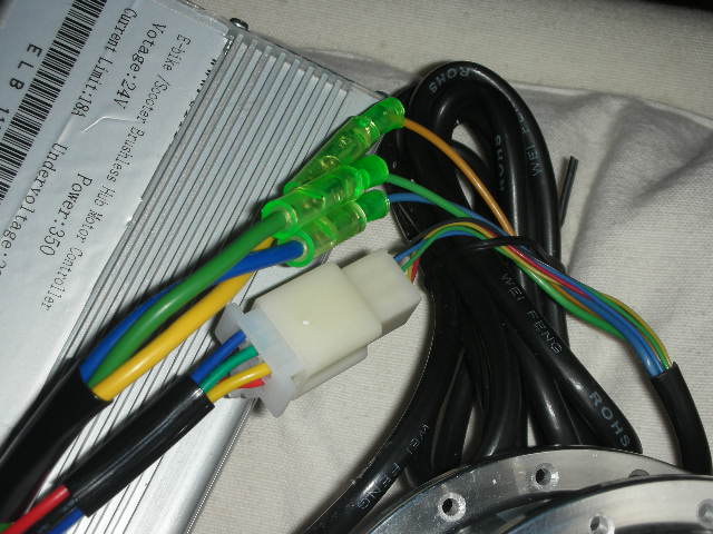
I´m trying to make work a 350W geared motor from elifefbike; also konwn as Ananda Cute Q85 or QQ-M85F with hall sensor(canwork also sensorless, according to them) so far unsuccessfully :oops: .
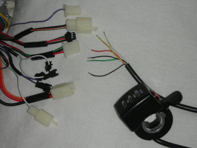
The controller is also from there 24V18a (with hall) E-CO09 (9Mosfets), the same origin applies to the Thumb Twist Grip throttle( Wuxing Brand) .
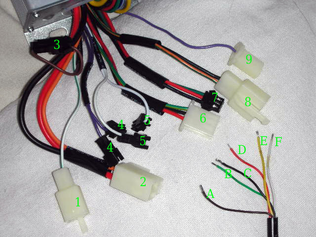
Well, when I bught motors in the past it easy to plug the wires right to each other: connectors just fit into the right place and usually with same colours but here :cry: . Woude anybody please help me? I wrote down numbers and letters in order to make it easier for everybody. The diagram the guy sent me i´ts also there. Thanks a lot in advance.
DSCN7824.jpg

DSCN7825.jpg

DSCN7826.jpg

94F1FG_6T7KD.JPG

http://www.elifebike.com/upfile/dtpic/2010/9W/9UJ7.992VA/1HE0AV_EF02J.pdf

P.S: I plan only to use throttle; no brake levers, regenerative breaking(it´s geared), no PAS, No horn , no lights nor similar.
 
My guess is that #6 on the controller is the throttle. The diagram shows what colors mate up on the three wires you need. The other three wires on the throttle assembly are not needed. You can hook up the green to your batt positive to make the battery monitor light work if you want but it is not required. Looks like the halls and the power just plugged in and matched in color. That is not always the case you are lucky there. You can often google the sites you purchased from or the numbers and names of the components to find hook up instructions/wiring info. Just a few jumpers will let you test things out before you hard wire them.
I have no idea what all the wires/plugs left are for but there is a chance the single whites and single purples on the controller, with mating plugs, may have to do with regen or motor cutoff. Controller is for a scooter so other plugs for lights/horn maybe a keyswitch ect. Hard to say without a complete diagram for the thing.
 
biohazardman said:
My guess is that #6 on the controller is the throttle...
Thanks a lot for your help...very nice place Portland with very good memories (Dog Mountain Hikes, Farmers´ Market...).
Let´s see whether this works.
 
Your last image is not showing for me so I don't know if you have this covered already. The #2 plug for the power has 3 wires: The red and black go to the battery and the orange goes to a key switch or to the battery positive. If you don't have the orange wire hooked up the controller will not power up.

Gary
 
GrayKard said:
Your last image is not showing for me so I don't know if you have this covered already. The #2 plug for the power has 3 wires: The red and black go to the battery and the orange goes to a key switch or to the battery positive. If you don't have the orange wire hooked up the controller will not power up.

Gary
Hi Gary,
thank you so much I.´ll try your pick and comment will follow on success (I hope). Last one it´s a PDF (already fixed): my fault.
 
biohazardman said:
My guess is that #6 on the controller is the throttle. The diagram shows what colors mate up on the three wires you need. The other three wires on the throttle assembly are not needed. You can hook up the green to your batt positive to make the battery monitor light work if you want but it is not required. Looks like the halls and the power just plugged in and matched in color. That is not always the case you are lucky there. You can often google the sites you purchased from or the numbers and names of the components to find hook up instructions/wiring info. Just a few jumpers will let you test things out before you hard wire them.
Hi again. Thanks for your answer; I´m making some progress: with black, red and white from the throttle attached to 6 in the controller(red-red, white-GREEN and black-black) the I plugged the battery into 2(red-red and black-black) with orange and red connected between themselves and the green wire from the throttle (green B in the picture) connected to red and/or orange (no difference since red orange are connected to each other now) and... IT WORKS... everything BUT the switcher(always on). What could I do now?
 
GrayKard said:
Your last image is not showing for me so I don't know if you have this covered already. The #2 plug for the power has 3 wires: The red and black go to the battery and the orange goes to a key switch or to the battery positive. If you don't have the orange wire hooked up the controller will not power up.

Hi again Gary. Thanks for your answer; I´m making some progress: with black, red and white from the throttle attached to 6 in the controller(red-red, white-GREEN and black-black); then I plugged the battery into 2(red-red and black-black) with orange and red connected between themselves and the green wire from the throttle (green B in the picture) connected to red and/or orange (no difference since red orange are connected to each other now) and... IT WORKS... everiything BUT the switcher. What could I do now?
 
The brown and yellow wires are the switch on the throttle. The orange wire from the controller, which is presently connected to the big red wire needs to have battery voltage to make the controller work. When disconnected, it puts the controller into stand-by mode. So, you need to cut it half way from the connector and join each end to the yellow and brown wires from the throttle, then you can switch between stand-by and normal operation using the switch on the throttle. A good idea is to connect the green wire to the controller side of the switch, then, when you put it into standby, the battery level indicator lights go off, and they come on when you switch to normal mode.
 
d8veh said:
The brown and yellow wires are the switch on the throttle. The orange wire from the controller, which is presently connected to the big red wire needs to have battery voltage to make the controller work. When disconnected, it puts the controller into stand-by mode. So, you need to cut it half way from the connector and join each end to the yellow and brown wires from the throttle, then you can switch between stand-by and normal operation using the switch on the throttle. A good idea is to connect the green wire to the controller side of the switch, then, when you put it into standby, the battery level indicator lights go off, and they come on when you switch to normal mode.
ok lets´try that thank you very much :D
 
It works!!!!!!!!!!! Thanks a lot to everybody :D
 
DSCN7824.jpg

Hi again.
Now I'm trying the very same but with the throttle only: no leds, no switch button... just a throttle with 3 wires red,green,black (letters b,c,d according to pics above).
Can I do it or will I need always a switch/display to make it work?
 
I am glad to see you were patient and got it running. The throttle needs no switch to operate but you should have one on the batts and the controller so you can turn it all off to save your battery from over discharge and damage. d8veh was talking about the physical/red on off switch button on the throttle I believe. It's a good one to use for turning the controller on/off for convenience and safety but you need some way of disconnecting the battery as well.
 
Just a reminder that however you do it - through a switch or not - the orange wire must be connected to the battery +ve for the controller to give power.
 
Back
Top