jamo96
100 W
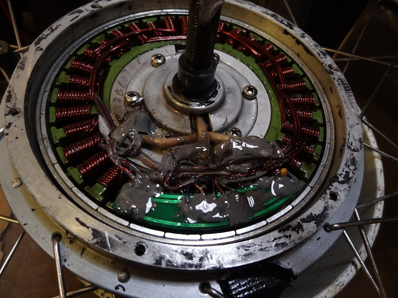
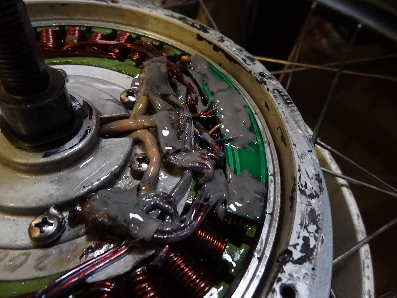
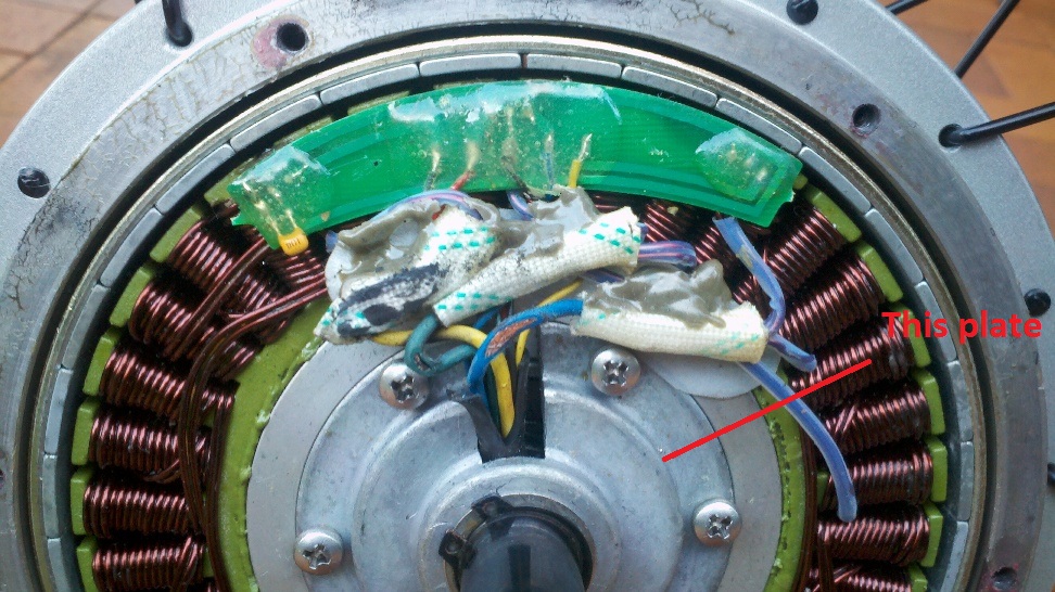
Is there a way to remove this plate from a MAC motor to make it a little easier to replace the phase wires?
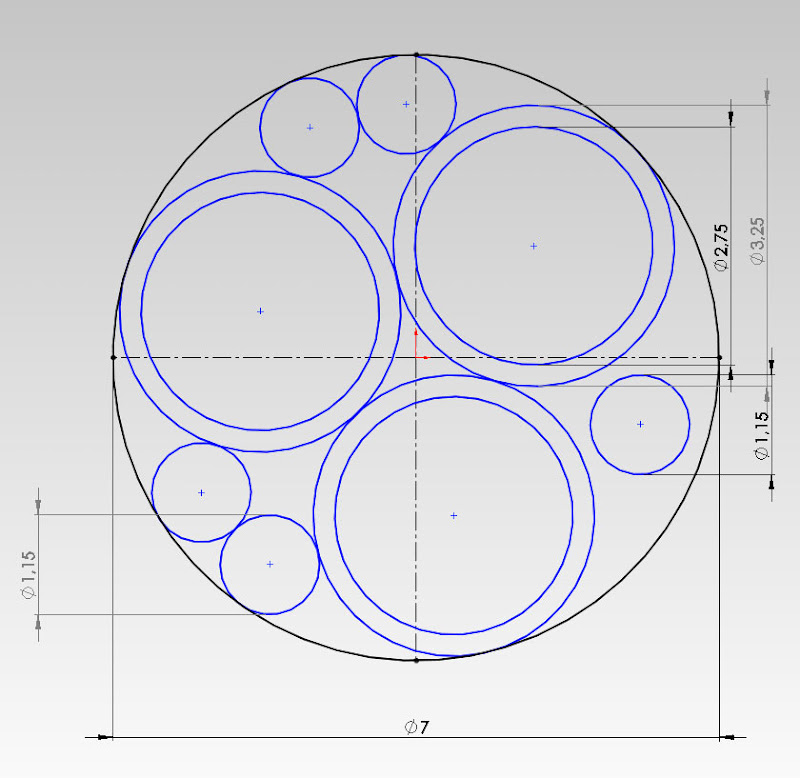
1000w said:I'm pretty sure its better to run a heavier gauge 'wire with thin insulation than a lighter gauge wire with thick insulation.
The heat issue in the standard phase wires is due to them being too thin, ie higher resistance, for the extra amps we wish to push through to the motor.
I fail to see how thick insulation can help with the amp carrying capacity of the wire.
Cheers,
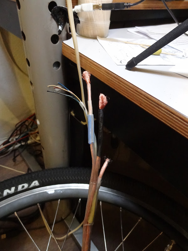
what i have done on the phase upgarde i have done for myself and others is tack all 3 phase wires out of the motor one at a time cliping the off the windings with enuff insolation left on to see what colour the phase wasjamo96 said:I've just got some 14 gauge teflon coated wire to replace the original ones (which i think were 14 gauge as well). I am not too worried about this I am turning the amps back down to a sensible level on my controller. The replacing is due to me testing my 24 Mosfet controller on this motor... bad idea haha.
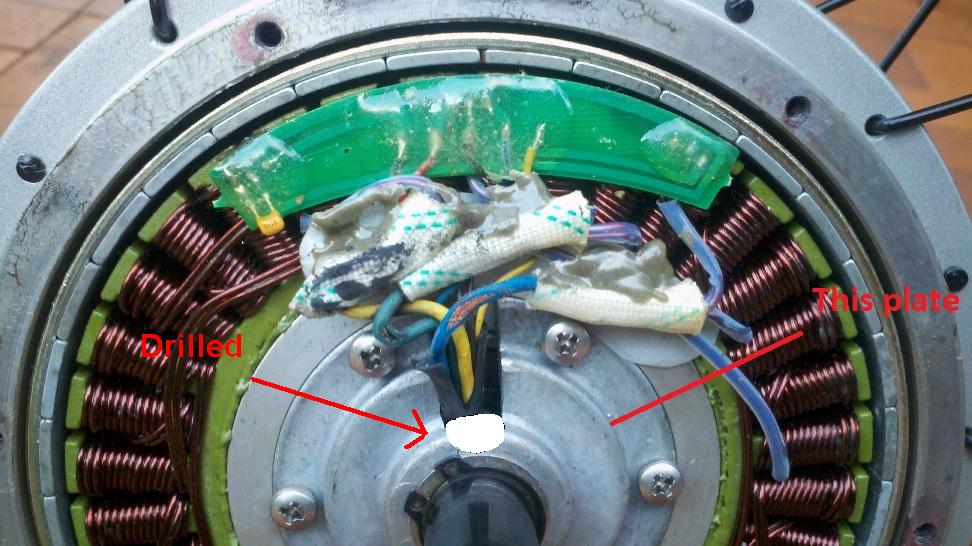
At the moment I cannot see a way to get them through without drilling or dremeling some more space where the wires exit the axle and come into the motor. Unless some one has done it before a different way.
nebriancent said:snake through first like this
s
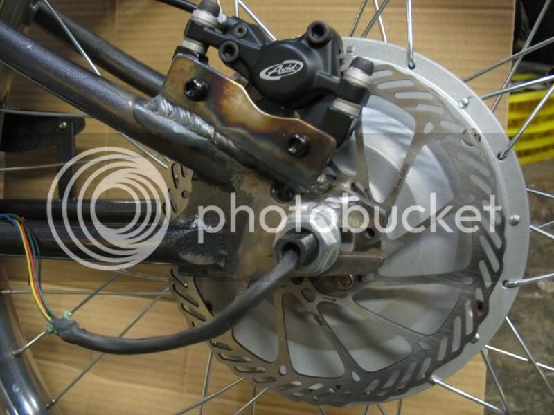
jamo96 said:I fed the wires through from the end of the axle and just bent them up slightly at the end and it was quite easy to pull them through with some needle nose pliers. Had to make sure not to strip the insulation off in the process as there is a sharp bend.
")
jamo96 said:I've just got some 14 gauge teflon coated wire to replace the original ones (which i think were 14 gauge as well). I am not too worried about this I am turning the amps back down to a sensible level on my controller. The replacing is due to me testing my 24 Mosfet controller on this motor... bad idea haha.
At the moment I cannot see a way to get them through without drilling or dremeling some more space where the wires exit the axle and come into the motor. Unless some one has done it before a different way.