Kelly Controller Pron, and a Call for Help

oatnet

1 MW
Joined
Apr 26, 2007
Messages
2,360
Location
SoCal, USA
ryis thread is for two purposes – one to document the basic wiring a Kelly BLDC controller with an xlyte (with possible side paths in how NOT to implement :D ), and I am stuck and could really use the help of someone smarter than me.

I purchased a Kelly KBL72101 BLDC controller – 72v/60a continuous, which is plenty of watts for my current project. My pre and post-sales emails went unanswered, but I ordered from the online store and it arrived from overseas in 9 days, 6 days faster than expected. The controller arrived neatly and securely packaged, with plugs for connectors J1 and J2, (pin 1 was broken in one of the plugs) and a couple of electrical components.

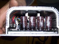
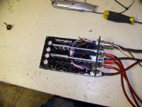
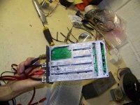
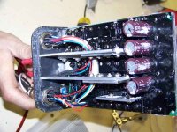
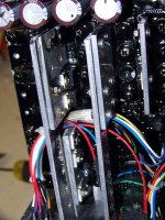
First off, For your Viewing Pleasure, some pictures of the Kelly side-by-side with an xlyte 72v20a and xlyte 72v40a “old style” controllers (click to expand images).
kelly_cont_1_top_2247.jpg
kelly_cont_2_front_horiz_2248.jpg
kelly_cont_3_side_2256.jpg
kelly_cont_4_quarter_2253.jpg
 
Connector J1 is for external LEDs, Can bus, reverse buzzer, etc so I won’t need it at all in this application.. Huge connectors for A/B/C and B+/B- stick out of the front and are fairly obvious, I’ll use rarebear’s (thanks rarebear!) recommended settings for xlyte on them as well is on the J2 connector in the next section. Reference:

http://www.endless-sphere.com/forums/viewtopic.php?f=2&t=3000&st=0&sk=t&sd=a&start=90
Motor: A blue / B green / C yellow
Hall: A yellow (13) / B blue (12) / C brown (11)

So, I started by wiring a connector for J2 for the Hall sensor and tthrottle connectors, as well as a power lead for the controller circuitry. Start with inner-ring pins 11-14 for the hall sensor, as they become less accessible when you solder pins on the exterior ring. Note that both throttle and hall connectors share Pin7 for power, as will brake/reverse if you use them.
NOTE – I am using an xlyte hall connector, but the wire colors on my throttle connector do not match xlyte, use the pictures below as a reference

Kelly Connector WireColor Xlyte connector
================== ======== ======== ===============
J2-Pin 1 (PWR) RED (TBD power source)
J2-Pin 2 (GND2) GREEN (Throttle)Ground
J2-Pin 5 (Throttle) YELLOW (Throttle)Signal/sweeper/throttle
J2-Pin 7 (5V Output) BLACK (Throttle)5V
J2-Pin 7 (5V Output) RED (Hall)5V
J2-Pin 11 (Hall Phase C) GREEN (Hall)Green{brown?}
J2-Pin 12 (Hall Phase B) BLUE (Hall)Blue
J2-Pin 13 (Hall Phase A) YELLOW (Hall)Yellow
J2-Pin 14 (GND) BLACK (Hall)Ground

View attachment 2
throtte_2262.jpg
connector 2263.jpg
 
Now here is where I am stuck. The picture below is an excerpt of the manual which is publicly available online from the manufacturer’s website here: http://www.kellycontroller.com/mot/Brushless-DC-Motor-Controller.html

wiring_circled.JPG

Unlike the xlyte’s, this controller appears to require a dedicated power line for its circuitry, instead of just tapping the main power line. If you are using 24/36/48v, apparently you can just run a separate tap from the pack. If you are running 60/72v, then you need to supply a separate feed (24v recommended), but I’d rather not add a DC/DC converter too. I run (2) 36v packs in serial for 72v, so I think if I run a lead from the first pack I can supply 36v to the controller logic and then run a lead from the second pack to B+ to supply 72v to the controller power stage.

However, I am completely mystified by the section in the red circle that gets power to the controller, what it does, why it even works. I am guessing that is some unspecified relay that connects motor power when you trigger controller power, but why bother? Does controller power need to come first?

So my questions to the gurus among us:

1) Instead of the junk in the red circle, Can I just put in a pair of simple power switches, one for the controller logic and one for the motor? If so, do I need to power the controller logic switch first or does it not really matter?

2) Should I put that “Precharge resistor” around the motor power switch anyhow, does it protect the controller from spikes?

3) Is my plan to pull a separate 36v lead from the first pack in the 72v series to power the controller logic circuit a sound idea?

4) I see where V+ is for the controller logic, but not V- . Does you think that controller logic power is grounding out to “B-“?

5) Has anyone tried this to work with a standard xlyte Hall-Sensor throttle? Do I need to modify it with a resistor or something? Due to the above power issue, I haven’t been able to power up the controller to see if it is actually an option on the setup menu.

-JD
 
Hi m8, I'm currently trying out a Kelly on the Puma, hope I can help.

1) THe junk in the red circle is a contactor, as used with brushed motors. THese are very usefull if the controllers have a tendancy to fail in the WideOpenThrottle position. Based on how we use x'l;yte controllers, I hope they will be OK without it, especially if your switch is easy to reach and can handle the power.
2)precharge resistor is a damn good idea, though I've been using the same switch for a few years now without one with no problems.
3) 36v for the controller I believe should be fine. somewhere lost in the manual it mentions " min PWR voltage 18, max 40v", and one communication with them hints that even 60v is OK. My feeling is they need to get this up to max pack voltage, or fit a 24v power out to feed the switch circuit.
4) not sure quite what you mean..
5)Mine works fine with standard x'lyte type throttle (halls)


My testing was cut short last week as I was away for the weekend, but i'll be back on the case tomorrow:)
I've got a few teething troubles with mine too, i'll open another thread about them this week!

Good luck :D
Steve
 
Thanks Steve, you filled in the blanks for me, I appreciate it! I look forward to your posts this week, really curious how the current limiting will work out.

On question #4, I am powering two separate circuits, the 36v controller logic via a lead from the first pack in the series, and the 72v power circuit via a lead from the 2nd pack in the series. It is obvious that the 72v circuit reaches ground via the B- connector, and I am assuming the 36v circuit also reaches ground via the same B- connecter. The question is more of a hangover from when I was thinking of powering the controller logic from a separate 24v pack - where would I have dropped the '-' lead - but I think the point is moot now.

How much voltage have you used on these? I'd like to leave my 88.8v peak-charged LiFePO4 packs connected, instead of disconnecting them to drain a few watts to get down to 82v, but I don't think it is gonna work out.

-JD
 
You are right that the 24 volt control line gets its - from the B-

I am using this on mine and it works fine.

I think 88 volts should be fine, I think you could actually go to 100 as that is the limits in the control program.

Have you downloaded the program and hooked into yet?
 
BE carefull for the moment with the PWR voltage, it seems my controller is now dead, i'm not sure yet whether this is because of overvoltage on the PWR line, or because the "j2" output socket was loose and has internally shorted. I will be postmorteming the controller when I get a spare here to compare readings. (I'll have another in 2 days, and shoulkd also have a brushed version soon too to try on the Perm132 motor).
88v on the main power bus seemed OK however. I'll find out what FETS are in it when I take it apart, and check voltage limits of the rest of the components too for your pleasure :)
 
Jozzer said:
BE carefull for the moment with the PWR voltage, it seems my controller is now dead, i'm not sure yet whether this is because of overvoltage on the PWR line, or because the "j2" output socket was loose and has internally shorted. I will be postmorteming the controller when I get a spare here to compare readings. (I'll have another in 2 days, and shoulkd also have a brushed version soon too to try on the Perm132 motor).
88v on the main power bus seemed OK however. I'll find out what FETS are in it when I take it apart, and check voltage limits of the rest of the components too for your pleasure :)

Sorry for your loss, but oh-so-eager to see the fiddly bits inside :twisted: . The controller has a very solid feel, I wonder if the guts are encased in that amberlike stuff.

So are you think it was the voltage you were supplying to J2 pin1?
Any chance it was from not having the contactor/precharge resistor?
I got (3) electrical components with my controller - one with a arge cylinder and two with small cylinders mounted on tape, and I don't know what they are, hoping one is a precharge resistor - do you know?

-JD
 
drewjet said:
You are right that the 24 volt control line gets its - from the B-
I am using this on mine and it works fine.
I think 88 volts should be fine, I think you could actually go to 100 as that is the limits in the control program.
Have you downloaded the program and hooked into yet?

I have downloaded the program, but I haven't hooked it up to power yet because I wasn't 100% sure where V- landed... but with your advice I'll hook a 24v battery V+ to J2:pin1 and V- to B-.

Are you using a DC-DC converter for the 24v? I was planning on pulling 36v from the first pack in the series, but I am also considering trying Fechter's dc-powered-ac-switching-power-supply trick instead. Hmmm, but then both the main 72v circuit and the stepped down 24v circuit would run through the same ground.

-JD
 
I am just tapping 24 volts out of my 75 Volt pack. So far seems to work OK.
 
If you got the same bag of bits that I did, the larger green components are the resistors, the small black ones with a silver end are diodes.

If you tap off the main pack, you will need to make sure you charge that 24v subsection seperatly from the rest, or balance the pack to compensate regularly, since the PWR line will draw a significant amount extra from those cells, leaving you with an increasingly unbalanced pack. (i measured 2AH drain after a few hours of fiddling/programming and such).
I'm sure it was nothing to do with lack of resistor/diode/contactor, and since the PWR line still powers it up I am not at all sure that overvolts on this part of the circuit was the cause of my current problem. It does seem that the controllerside part of the dinplug connectors are both loose enough to rotate freely in the casing, I wouldnt be surprised if something was shorting in there. I've got "permission" to take it apart, and will do so tomorrow.

How are you getting on with yours?
 
Jozzer said:
The larger green components are the resistors, the small black ones with a silver end are diodes.

Thanks!

Jozzer said:
If you tap off the main pack, you will need to make sure you charge that 24v subsection seperatly from the rest, or balance the pack to compensate regularly,

I'm actually gonna pull a full 36v from one of two packs in series for 72v - so that one entire pack will drain lower, but I am not likely to come close to using the full LiFe pack that will go on this post-testing.

Jozzer said:
It does seem that the controllerside part of the dinplug connectors are both loose enough to rotate freely in the casing, I wouldnt be surprised if something was shorting in there.

Aww shoot I noticed the same thing on my J2 whilst I was fitting the plug to it - it seemed to rotate 1/4 turn counterclockwise. I hope I don't face similar issues.

Jozzer said:
How are you getting on with yours?

I spent yesterday tidying up loose ends my test mule for this (5305 xtracycle) and connectorizing (4) 36v5ah NiCd packs I got from Johnbear and ebikes.ca "battery sale" - they shoud be pretty indestructable, I'll replace them with LiFe once I have things sorted, and it should give me a really good idea of how smoothly the current limiting is enabled. OTOH it felt pretty peppy with an xlyte 72v20a controller yesterday, and an xtracycle is a good place for all that heavy NiCd, maybe I'll just leave it there...

So today I'll build a switch/circuit breaker/distribution box, bolt it up and see what I get!

-JD
 
Centrespread?
Seems a Fet or two are blown :| The spec on the Fets doesnt seem great (forget the number now, will edit it in tomorrow from work)
The black potting is sploshed over moist components, but all part numbers are intact underneath it.
The rotating plugs seem nothing to be concerend about (as long as they dont rotate more than a little).
I suspect this one blew because the FETs couldnt handle a Puma, but we'll see!
 

Attachments

  • 100_0196small.jpg
    100_0196small.jpg
    51 KB · Views: 7,215
  • 100_0197small.jpg
    100_0197small.jpg
    40.7 KB · Views: 7,212
  • 100_0198small.jpg
    100_0198small.jpg
    48.4 KB · Views: 7,208
  • 100_0199small.jpg
    100_0199small.jpg
    66 KB · Views: 7,203
  • 100_0200small.jpg
    100_0200small.jpg
    66.3 KB · Views: 7,195
Wow Jozzer, the first views inside the Kelly! It is a nice looking build inside, now I see why it felt so solid in my hands, too bad the fets are unimpressive. What v/a were you running the Puma at?

Hmm, after seeing those heat sinks on the inside, I am going to mount the Kelly with the flat side down, to help wick heat up and away from the circuitboard instead. I thought the Fets were mounted on the bottom, with the big plate there to cool them.

I spent the day (vacation, Hah!) making the wiring harness below for the Kelly controller, so tomorrow I can finally play with it - yay!

-JD

wiring harness2280.jpg
 
Oh no it is potted sort of. That sucks. Thanks for the first view inside the controller.
 
I'll poke a camera anywhere me :shock:
In general I run at around 2.5KW,, i saw that figure out of the kelly at higher speeds on the "speed" setting, so I guess for you x'lyte guys at least it will work at full power on the "torque" setting?

Me looks out window for the deliveryvan carrying my second controller.

I also have a kelly brushed controler here, but alas dont have anything ready to try it on (its 48v, my brushed vehicles have 80v packs).
 
Nice pics Jozzer thanks for posting.

The manual states (section 3.1) that

To ensure full rated output power, the controller should be fastened to a clean, flat metal surface with four screws. Applying silicon gel or other thermal conductive material to contact surface will enhance thermal performance.
Sufficient heat sink and air flow is required for high power application
It should have over temperature protection also.

Jozzer said:
The black potting is sploshed over moist components.................

Er?...Get help Jozzer. :lol: :lol:
 
Jozzer thanks again for sharing those pics I was looking at them a lot today.

To ensure full rated output power, the controller should be fastened to a clean, flat metal surface with four screws. Applying silicon gel or other thermal conductive material to contact surface will enhance thermal performance.
Sufficient heat sink and air flow is required for high power application

Funny, I did just that on my last build, I mounted a 2nd gen xlyte controller to an aluminum surround that ducted air past the controller... It proved out well for a month on a 5305, but after I swapped the setup to a 5304, the first time I ran it hard on a 5304 it blew, leaving me stranded 5 miles away. Guess the extra current draw of the 5304 was just a little bit too much for it - maybe if I had used more thermal grease <grin>. Mounting to sheet steel this time, and with that big bottom plate I was planning on slathering on the the thermal grease.

Anyhow, more progress today. Got some nice metric bolts at Ace Hardware that fitted the holes snugly, bolted on the battery any motor power leads. I had a bit of trouble getting bolt through the 'B' motor lead, it is way too close to the J1 connector, and in fact now that it is in I don't think I'd bve able to use the J1 connector - good thing I don't need anything on it.

It powered up and programmed on the first try, but when I tried it on a bike it gave me a throttle error (2,4). I tried a bunch of settings, different throttle, no luck. I pulled the J2 connector off - BTW don't screw down the locking ring on the J2 if the connector side is loose like mine and Jozzer's - it was a serious pain to get bck off. with the harness out, I ohm'd out the pinouts (all correct), plugged it back in to the controller and hooked it to the bike and everything worked. Maybe all the pins weren't seated on the J2 connector, dunno. Now I am working on the mount for the controller and in a day or so I hope to have an interesting bike to show!

It occours to me that when I hard mount this to my bike for theft resistance, it will be a bit harder to program. Wonder if I have any 25' seral cables still around?

I see the overvoltage warning on the slider goes up to 92v - I wonder if my 88.8 LiFePO4 will be OK after all?
What is the deal with the Torque vs Speed mode?
Hmm... I wonder if the TF brake sensors would work on this controller.

-JD
 
Re torque vs speed, the speed setting gives very harsh current limiting at startoff, only allowing more power as the motor speeds up. THe torque setting feels much better, except that it doesnt seem to work on the Puma properly, its cuts on and off (like, it pulls for 2 secs, then stops for a sec, then pulls for a few, then stops). Not sure yet if this is a puma related problem, or I had a fualty controller. Perhaps you can test yours so I have more info on what it does with other motors?

The Mosfets were rated 100v I believe, you should be just about clear (by 88v, you mean fresh off charger? not nominal voltage?)
 
Thanks for the inside pics :D

Too bad that ugly potting compound hides most of the interesting details.

Any idea exactly what caused it to fry? The inductance of the Puma motor is quite low, so that might be part of it.

It also sucks that it doesn't have an internal voltage regulator to supply the 24v (or whatever) to power the logic. Seems like it wouldn't be that much more expense to do it the same as Crystalyte did.

If you use a switching power supply as a dc-dc, it will work fine even though the B- sides are in common. I wonder how much current the 24v circuit takes? I bet it's not much. A small power supply might fit inside the case.

Weird about the surging behavior in the current mode too. That doesn't sound right. Perhaps there is something in the software that can fix that.
 
Per Kelly, the draw is only 100 MA. Very little draw.
 
Yah I read that it needs a supply voltage and I think that is just sad. The alltrax and other controllers seem to have it figured it out. Well more Dc-DC the better.
 
No idea why it fry:( It was with no throttle, I was just conecting it up, and the fuse blew. It was the pwr line I was connecting when it blew, not the battery leads I believe (although the exitement may have clouded my memory, since my nose was close to the fuse when it popped and flashed and I was somewhat surprised:))

A freind commented "OMG, They killed Kelly!"

Still waiting for the other one, should have been here yesterday:(

If anyone wants pics of the insides of the kelly brushed controller, let me know and i'll denude her!
 
drewjet said:
Per Kelly, the draw is only 100 MA. Very little draw.
Is that number from the manual or did you get it from them directly ? Is that the worst case ? Can someone with a working setup measure the current on PWR line please ?
I am deciding if I need a dedicated 24V DCDC converter or simply tap one of the two series connected 33V packs.
 
Back
Top