How to change my throttle output signal

Hugues

1 kW
Joined
Aug 7, 2011
Messages
434
Location
Switzerland
Hi guys,

I'm looking for a not too complicated way of changing the way my throttle behaves (hall effect). You can see in the chart attached the Voltage in relation to the throttle position, for simplicity i measured the voltage at 8 different positions between closed and fully opened. That's the blue line. The red line is what I would like to achieve instead. There are 2 things that bother me with my current setting:

- the twist angle is too wide from zero to fully open. I don't like to twist that much, and also, as throttle power is not quite legal here on a bike, i would like it to become a little more "discreet" when i twist it.
- second thing is that there is a nice burst of power by the end, the blue line clearly shows it, and i would like the output to be more linear, or even a bit curved, slowing down towards the end.

So the output i would like is the red line. (motor starts spinning at around 1.5 V)

Is there a not too complicated way of achieving this ? I checked inside the throttle to see if i can bring the 2 magnets closer in order to reduce the twist angle, but these are nicely glued in place and the risk of breaking them is high.

Any simple electronics on the signal line could do the trick ?
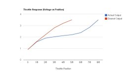
throttle output.jpg
thanks a lot,
 
Most of us would like a more progressive curve, funny that you are looking for the opposite.

There would be a good demand for an adjustable throttle, or one that would not kick too hard from the start. All my bikes have a twitchy throttle, that can flip the bike upside down if one is not aware and careful. I set them with 3 speed switches, that helps when I let some friend ride one of my bikes. The controller can be programmed for those 3 throttle levels, setting yours at 120 % throttle would make the response curve steeper, and that may be enough to meet your requirement.
 
MadRhino said:
Most of us would like a more progressive curve, funny that you are looking for the opposite.

....

well, depends on which part of the curve.

the initial part of mine is very smooth and comfortable, not twitchy at all.
It's the somewhat flat part that i don't like, and the final burst that is too far.

If we could set this up like on RC radio controls, that would be great.

I could live with my current curve, but i would like to compress it a bit.

Not ready to go in programming mode for now.
 
Hugues said:
the initial part of mine is very smooth and comfortable, not twitchy at all...
That is because of low power, if you'd feed a motor 7Kw, it would be very twitchy. :wink:

Programmable controllers are easy to set, if yours is you should try setting 120% throttle. Using a software is much simpler than doing electronics mods, for me at least.
 
You can use a PIC chip like the Picaxe or whatever equivalents you have. You can use the throttle 5v to power it. As it doesn't have analogue out, you have to PWM the output and then use a low-pass filter (resister and capacitor) to convert the digital to analogue output. Use the throttle signal as an input and you can program the output to anything you want. It might sound complicated,but you can get a ready-made board and programming lead for about $25. Programming is really easy by a simple flow-chart interface. There was a thread similar to this about 3 months ago, where a guy did a schematic and offered the program code as well. You'll need to do a search. If you go this route, you can do some really cool things like adding continuously variable speed control, boost buttons or whatever.
 
If pedelec is required, use a pedal sensor to "enable" the throttle, so after you stop pedaling for a couple seconds it cuts the throttle, That will remind you to pedal even if not propelling the bike.

The Magura throttle is resistive and very linear. It turns farther than you want, but by adding appropriate resistors you can make a nice straight curve.

Using a small micro to get a programmable curve would be the most flexible way to go, if you are up to the complexity. The little picaxe chip mentioned above is about as simple as they get, and really simple to program.
 
Here's the link:
http://endless-sphere.com/forums/viewtopic.php?f=2&t=33963&p=494371&hilit=throttle+signal#p494371
 
If your throttle is the kind with two separate magnets, you might be able to glue a small piece of magnet near the end of the high side magnet to reduce the angle of twist. Even a piece of steel might do it.
 
Thanks for the inputs guys, appreciated.


fechter said:
If your throttle is the kind with two separate magnets, you might be able to glue a small piece of magnet near the end of the high side magnet to reduce the angle of twist. Even a piece of steel might do it.

I was just thinking about that actually. Just to be sure I understand how these 2 magnets work:
- at zero throttle one magnet is touching the hall sensor
- then it starts to move away
- at 50% throttle both magnets are at equal distance of the hall sensor
- then at 100% the second magnet comes in contact with the hall sensor

So if I manage to insert a new magnet between the hall and the second magnet , then I guess the flat part of my curve will be reduced, right ?
 
You could fit a CA and tell it to consider 2.5v full throttle, it will then proportionally split the the movement between closed and 2.5v equally to give a progresive action.

Simon.
 
Tench said:
You could fit a CA and tell it to consider 2.5v full throttle, it will then proportionally split the the movement between closed and 2.5v equally to give a progresive action.

Simon.
Tried that but did not work
Tried any value

Unless you meant to switch to a current throttle ?
I've read about that but seems some people did not like the way it behaves
 
Yes, the CA will need to be able to create the required signal from the throttles imput for it to work so the throttle will need to be wired onto the CA board, i agree the initial take up can be a little abrupt but with fine tuning of the upper and lower limits i managed to get ours to behave exactly as i wanted it too.
 
Hugues said:
Thanks for the inputs guys, appreciated.


fechter said:
If your throttle is the kind with two separate magnets, you might be able to glue a small piece of magnet near the end of the high side magnet to reduce the angle of twist. Even a piece of steel might do it.

I was just thinking about that actually. Just to be sure I understand how these 2 magnets work:
- at zero throttle one magnet is touching the hall sensor
- then it starts to move away
- at 50% throttle both magnets are at equal distance of the hall sensor
- then at 100% the second magnet comes in contact with the hall sensor


So if I manage to insert a new magnet between the hall and the second magnet , then I guess the flat part of my curve will be reduced, right ?

The two magnet hall throttles use an interesting magnetic configuration. The low side magnet (closest to sensor at zero throttle) is magnetized radially, that is the poles are faced 90 deg to the direction of movement. The magnet on the high side is magnetized with the poles parallel to the direction of movement.
If you attach a piece of magnet to the high side in it's naturally attacted direction, it should make the travel shorter.

The little magnets on a Sonicare toothbrush head are about the right size. It's possible to grind the magnet material if the piece is too large, but be careful to avoid overheating the magnet. You should be able to test without actually gluing the magnet, as the magnetic force will hold it in place. If you can get a satisfactory arrangement, then glue it.
 
That was a very good call Fechter :idea:

Do you think that we can use the same effect to do the opposite ?

I mean, changing the lower magnet field to make the throttle signal curve more progressive.
 
MadRhino said:
That was a very good call Fechter :idea:

Do you think that we can use the same effect to do the opposite ?

I mean, changing the lower magnet field to make the throttle signal curve more progressive.

Hmm... now that might be easier with a microprocessor. :shock:

Actually, you could probably mess with the magnetic field to get that effect. I think the way to do it would be to make the high side magnet thinner so it has less dipole moment. Making it weaker might have a similar effect, but it still needs to make the hall sensor go full throttle, so you can't weaken it too much.

If you remove the high side magnet and replace it with a thinner one, you could vary the spacing of the magnet such that it just reaches full throttle when you fully advance it. Slightly angling the magnet will change the response too. A drawing would be good here. It's very easy to bench test though. You could probably get away with a 9v battery and a voltmeter. A 5v supply would be better since that's what the throttle normall runs off.

I'll have to think about it, but there may be a way to place some iron in the magnetic path to get a more progressive low end using the stock magnets.
 
@Madrhino
By opposite you mean a more gradual start ? If so, here's my hypothesis:

- first magnet, the one in contact with hall when throttle is at zero position, or low side, is responsible for first part of the curve
- when this magnet slowly goes away from hall sensor, magnetic field is reduced, and this is translated into an increasing voltage
- so if you want this increase in voltage to be less rapid, then one way could be to increase the strength of the magnetic field on low side
- you can test this hypothesis by using a bigger magnet or a second one next to it, depending on the space available.

My two cents
 
@ Fechter

This should be easy to try and experiment with, maybe the solution for a more progressive throttle can be as simple as the one to make it more linear.

@ Hugues

Yep, most of us building high power have that same problem with the throttle lacking precision at the beginning of its travel, making the control very twitchy at lower speed. Making the throttle signal curve to start smother would help controlling the acceleration. Ideally, it would be precise enough to control and sustain a wheelie, just as good as with an ICE bike.

Since you had success playing with the magnet configuration to change the signal curve, it would be logic to think that an adjustable throttle signal curve is possible with simple mechanical positioning of the low and high magnets, or maybe with an interference in the magnetic field that could be moved along the throttle travel.
 
i have another bike with the same battery power and motor, but a different throttle, i think it's the one sold by ebikes.ca, not sure.
On this bike, although it's the same power, the throttle is very brutal at the start.

i think it depends how the electronic on board the throttle converts the hall sensor signal, what is the strenght of the magnets, how far apart are they from the hall.

Depends also of course how the controller translates this volatge into an output. But on both bike controller is the same.

My current throttle can turn the motor at a very low rpm, probably one turn per second or less. I bet it can do the same on your more powerful setup ,

can you graph your throttle output voltage as i've done in my initial post ? i would be interested to compare. I'll do it with my other funky throttle too.
 
My throttles are those half grip sold by Lyen, I'd say their signal curve is quite linear, and I would like to have it much more progressive in order to reach 50% of power at about 75% of throttle travel. Yet, the bikes power configuration changes very often, for I swap motors and controllers. So my need is really for an adjustable throttle, if I want to be able to control the wheelie as with an ICE bike.
 
I know it helps if the controller is well matched to the throttle output at the low end. This can be done by adding a variable resistor to the ground wire on the throttle and adjusting until the motor just stays off at zero throttle.

If the controller doesn't start until the throttle is advanced a fair amount, it starts out on a steeper part of the curve.

To make the output more progressive, you'd need to either make the low side magnet stronger or the high side weaker. Problem is there isn't much room inside the throttle for adding stuff.

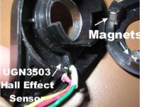
Here's a pic of the insides of a two magnet throttle (from Goldenmotor):
Hall Throttle insides.jpg

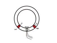
The orientation of the magnets is like this:
Hall throttle magnets.jpg

The sensor only responds to the field in one axis, so when it is close to the low side magnet, the field is 90 degrees to the sensor axis, so the output is zero. As the throttle is advanced, it gets closer to the other magnet, which is aligned parallel to the sensor's axis, so the output is maximum.

If you could add an extra magnet to the low side, perhaps on the outside dia, that was oriented the same as the existing low side magnet, you could extend the low end. Similarly, if the high side magnet is smaller, it's zone of influence will shrink, extending the low end.

A strip of steel around the outside diameter that starts over the low side magnet and ends about half way might do something.
 
Back
Top