Upgrading Lyen Controller Traces

Joined
May 2, 2012
Messages
60
Location
ontario canada
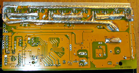
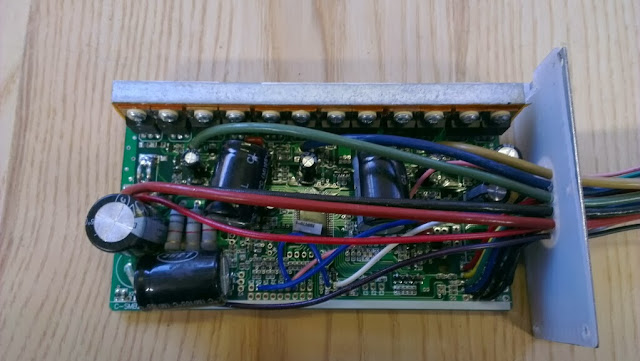
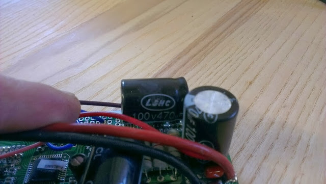
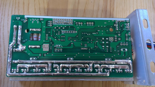
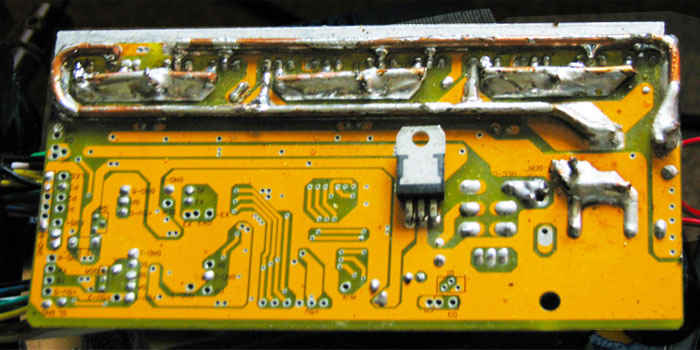
I have some copper braid and a 140 watt weller soldering gun. I decided to upgrade the traces on my 12 fet sensorless lyen controller. So i went to use my soldering gun, and tinned my tip/braid. But the gun just cant melt the solder on the broad. The braid just wont stick even with flux.

How can a 140 watt soldering gun not melt the traces? Is there a butane soldering iron for more powerful stuff that i can use? The biggest soldering iron I have found locally is 200watts which really isnt that much more.

IS there a DIY trend on ES about upgrading traces that i can read?

Thanks guys
 
I use a very old 45W Weller temperature controlled iron, and it works fine for soldering heavy copper like this. The secret is to use a big tip on the iron, with a lot of thermal mass. The iron I have has interchangeable tips, so I just fit a fairly broad one (usually either a 700 deg F or 800 deg F rated one) and this works perfectly well.

I suspect that the gun you have only has a bit of fairly thin wire as a tip, and this may well be why you're struggling. A temperature controlled iron that will accept a fairly big (say, around 3/16 wide angled flat, with a fairly blunt taper back to where it fits the iron, to give a fair bit of thermal mass) should do the job OK.
 
http://ecx.images-amazon.com/images/I/61hoZ6hcXyL.jpg

If you can see this pic, it is the bottom soldering tip. Its round and flat to provide lots of connection area.
 
appleseed123 said:
http://ecx.images-amazon.com/images/I/61hoZ6hcXyL.jpg

If you can see this pic, it is the bottom soldering tip. Its round and flat to provide lots of connection area.

It has area, but the secret is thermal mass, as I said above, and these bits are really very thin and low in thermal mass. Thermal mass means having a nice, thick, bit, with enough material (ideally copper) in it to be able to hold and conduct heat quickly to the item being soldered.
 
Here is what I use for doing the traces and battery bars. Nice 3/8" tip.
http://www.amazon.com/Weller-80-Watt-Soldering-Iron/dp/B00018AR3Q/ref=sr_1_1?ie=UTF8&qid=1349631297&sr=8-1&keywords=weller+80W

First you want to heat the trace and pull out the tiny tin wire. I usually start fresh and remove most of the solder first with copper braid/flux. I have almost the whole trace heated so the solder is molten, but you don't want to hold the iron on there forever; or you could damage the traces or have something come ungluged. Flow is key so you dont get any hidden breaks or anything. You must be carefull around the mosfets and be sure not to have anything fall down from the other side. Through hole capacitors are on some of the traces so be careful around those. I use solid copper wire so I have to tack down the ends and area's first before I flow a bunch of solder on. Each piece bent into the shape it needs to be first.

Here are some pics of the traces on this board I did: http://endless-sphere.com/forums/viewtopic.php?f=2&t=17680
 
Jeremy Harris said:
appleseed123 said:
http://ecx.images-amazon.com/images/I/61hoZ6hcXyL.jpg

If you can see this pic, it is the bottom soldering tip. Its round and flat to provide lots of connection area.

It has area, but the secret is thermal mass, as I said above, and these bits are really very thin and low in thermal mass. Thermal mass means having a nice, thick, bit, with enough material (ideally copper) in it to be able to hold and conduct heat quickly to the item being soldered.

yes, i understand thank you. I guess solder guns in general dont have much thermal mass. As soon as i touch the soldering gun to the trace the solder on the gun cools. I guess I will look for one that has a bigger tip like Tmaster has.

BTW tmaster, you build is awesome but alittle over the top for me. Since copper is so much better than solder for conducting, i just wanted to help it out abit by adding a braid. Your controller is way OP for what i want, which is 50 amps and stays cool.

Thanks guys.
 
The 12 fet controller is already 45amps. 50 is not much more, and not really worth upgrading the traces.
 
I know but i am kinda doing it for experience and abit for more reliability if i want higher phase amps. I just like to tinker with my stuff really.
 
I haven't tried these on circuit boards, but they are wonderful for large connections. I only use my soldering irons for small stuff now.
http://www.ebay.com/itm/Lot-of-3-Big-Bottle-Shaped-Butane-Cigarette-Cigar-Torch-Lighter-93029-x-3-/261015254395
 
Just an update, i got a bigger soldering iron. 3/8ths and it work wonderfully. i was surprised that the traces would absorb the heat faster than 140watts replaces it. The ebike is working perfectly and i will do a total build on it when i upgrade the batteries finally.

Big shout out to everyone on the forum that helped me. COuldnt have done it without you guys
 
Hi. I have a question regarding controller. I have a greentime 72V 50amp controller. I will be running CL HS3540 hub. Is there a potential to mod the controller or more current will kill the hub? If i understand correctly at 50amps i would do 4380 watts hot of charger. If it would be beneficial how far would water cooling allow controller to go? It is not programmable controller so what way it is done?
Here are couple photos of controller, it is 12 FET:
IMAG0919.jpg

IMAG0922.jpg

IMAG0924.jpg

The FETS are IRFB4110. Thought would be nice to get involved with modding controller. For waterblock i thought i would take 2 15x5mm copper flat bars and route a 2mm grove in both of them. Than solder them into one block and drill two ends to solder end pipes in. I would then use termo switch to turn on the pump at certain temp and run it of dcdc. Was thinking on PC water pump at 600L/h.
Any thoughts on this?
 
The mod used on the smaller KU63 to increase current fairly reliably (just adding a single small resistor to the current sense circuit) should work with this controller, as in reality it's also a Wuxi controller re-badged by Greentime, the same as the KU series or the Hua Tong controllers. See write up on this web site for details of that part of the circuit: http://www.avdweb.nl/solar-bike/electronics/ku63-motor-controller.html#h0-1-1-similar-ku-seriesanbspmotor-controllers
 
Jeremy Harris said:
The mod used on the smaller KU63 to increase current fairly reliably (just adding a single small resistor to the current sense circuit) should work with this controller, as in reality it's also a Wuxi controller re-badged by Greentime, the same as the KU series or the Hua Tong controllers. See write up on this web site for details of that part of the circuit: http://www.avdweb.nl/solar-bike/electronics/ku63-motor-controller.html#h0-1-1-similar-ku-seriesanbspmotor-controllers

Thanks for the link. Really easy mod to do myself. The only question still standing is by how much and if water cooling would make any difference as i am eager to try, never had a chance to work on PC water blocks.
 
agniusm said:
The only question still standing is by how much and if water cooling would make any difference as i am eager to try, never had a chance to work on PC water blocks.

Probably not a lot, as the main issue with these small TO220 package FETs is the thermal resistance inside the FET package, from the FET silicon die to the heatsink. Typically the FET will have a thermal resistance of around 1 deg C per watt from the die to the heatsink insulator, plus maybe another 0.5 deg C per watt across the insulator (if you use something thin, like Kapton tape, more if you use the silicon insulator pads). This means that you have around 1.5 deg C per watt of fixed thermal resistance. If the standard case has a thermal resistance of, say, 2 deg C per watt, and you can maybe halve this by using water cooling, then in reality all you're doing is going from a total of around 3.5 deg C per watt to about 2.5 deg C per watt. It might make a small difference, but overall I doubt it'd be worth all the hassle of doing. At 50A I wouldn't have thought that IRFB4110s would generate much heat anyway.

One advantage water cooling does give is that it allows you to locate the controller inside a closed box and just have the radiator out in the airflow. This may be an advantage in some installations, where space is tight.
 
Thanks. This is good. I was thinking in enclosing all the stuff for more sleek build and making air inlet to cool radiator, perhaps if i squeeze out 10amps, that would be good enough to take on this task. Thanks again for the inside view on fets, i read quiet few of your posts regarding FET thermal dissipation and formulas didn't made a lot of sense but these numbers do. Good job there.
Cheers

I wander if anyone done cooling using peltier cooler method as that can freeze below zero C. only they consume lots, still could be beneficial for hill climbing, acceleration situations.
 
I cannot imagine a situation that you would be better off using a peltier on a bike, than a more traditional cooling method. They are very very power hungry, it's not worth it even for the most high capacity bikes to waste 50-200w on lowering the temp your fets see. The effort would be better spent on getting a bigger controller if you need more power, improving the air cooling, or adding water cooling.

I am actually building a 36 fet water cooled controller at the moment. Look around at what other people have done to get high power, reliable controllers. Thread here: http://endless-sphere.com/forums/viewtopic.php?f=2&t=43369
 
agniusm said:
I wander if anyone done cooling using peltier cooler method as that can freeze below zero C. only they consume lots, still could be beneficial for hill climbing, acceleration situations.
It's been thoroughly debased and not worth it. Search ES on "peltier".

For trace upgrades I have used braid (don't bother), standed wire in 12 & 10 AWG (PITA), and solid copper wire in 12, 10 & 8 AWG (easiest to work with). The reality is that we're upgrading DC power traces, not A/C, so we don't need braids or strands when solid copper will do. And we want as little solder as possible.

Recently I noticed my local electrinics supply was carrying flat wire although I forgot to note the equivalent AWG. Seems tempting, structurally stronger, as a fin - radiates heat better, and generally easier to bend. I have two controllers waiting for trace upgrades; inspired by others that have tried it - I might go that route and report on the results.

My ½ W, KF
 
Kingfish said:
Recently I noticed my local electrinics supply was carrying flat wire although I forgot to note the equivalent AWG. Seems tempting, structurally stronger, as a fin - radiates heat better, and generally easier to bend. I have two controllers waiting for trace upgrades; inspired by others that have tried it - I might go that route and report on the results.

My ½ W, KF

I did something similar on a low voltage, high current controller I made up for my boat. I cut some strips from 18g copper sheet and soldered it on edge to the traces. Worked very well, and as I was fitting new FETs I was able to solder the FET leads up the side of the copper. Only downside is that it wouldn't have fitted into the standard case, as the strips reduced the clearance a bit too much.
 
tostino said:
I cannot imagine a situation that you would be better off using a peltier on a bike, than a more traditional cooling method. They are very very power hungry, it's not worth it even for the most high capacity bikes to waste 50-200w on lowering the temp your fets see. The effort would be better spent on getting a bigger controller if you need more power, improving the air cooling, or adding water cooling.

I am actually building a 36 fet water cooled controller at the moment. Look around at what other people have done to get high power, reliable controllers. Thread here: http://endless-sphere.com/forums/viewtopic.php?f=2&t=43369

I read your topic few times, was waiting on updates. i think that soldering pipes to a bar of copper would not be as effective. I think copper layer should be minimal as to transfer heat to coolant more efficiently. i like fet compression method but it looks a bit bulky.
Peltier was just a glitch in my head, i knew they are monsters on current.

Flat copper wire is good i think as well.
 
Jeremy, that sounds quite familiar… did you post on that work? Creative solutions like that always bring a smile. Height is definitely a concern and why I prefer square shape as a better ideal solution – if it can be had.

Just checked with eBay and there’s nothing available in 12 or 10 AWG for square magnetic wire. MWS Wire Industries has a good selection spec – but no pricing on minimum quantities (I fear to ask). It would be great to have a couple of meters each just to play with.

As an alternative, I know of one manufacturer that will slit copper sheet.

DIY: A couple of years ago I took 10-AWG solid copper and lightly hammered it flatter; not the preferred route. However - it worked.

EB212.mod.bot.jpg

March 27, 2010 - my 1st 12-FET controller. It was recruited as the RH slaved-controller for the 2011 road trip.

Searching for square sources, KF
 
I agree that how I did it may not be perfect. I may go back if it doesn't work too well, and notch the bar and embed the pipe, then re-solder. All depends.

The compression is pretty bulky, but managed to fit everything into the project box no problem, so it doesn't bother me. I'll have an update in a couple days. I managed to get the controller to spin my motor last night.

Best of luck =).
 
Thanks Dennis :)

ADDENDUM: I just want to be clear and say that I am running about 18 to 24 Battery Amps on my controllers – however I am also keen to reduce resistance wherever possible to reduce potential for sag. Upgrading traces was the first and easiest item to affect (relatively speaking – as opposed to replacing the entire battery harness, which eventually I did).

Also, it’s difficult to observe, however the smaller traces leading off of the upgraded copper bus have smaller-gauge copper wire at the core. The best method I’ve seen employed is when building a new controller and the FETs leads are bent over the traces – beefing them in the process. However – unless you are completely geeked to achieve perfection, it’s a lot of detailed work to de-solder and rip off the old to emplace the new, and there’s a real chance of frying the trace to a crisp and lifting it off the board – causing more damage than benefit. Short story: Be careful out there; a good hot iron makes a huge difference.

P1-FH-12FETController.jpg

Sept 9, 2012 - Lyen 12FET beefed using 10-AWG stranded. I ran out of solid copper. :wink:

Best o' luck, KF
 
i noticed the little stumpy pieces. you also added some buss bar to the shunt connection trace too. but i think it valuable that people notice how you only used a little solder where the solid wire was tacked down, in the critical spots. this is how the pros do it. using solder wick or heavy braid saturated with tons of solder doesn't make a lot of sense to me since the copper conducts so much better than the solder they use to assemble them.
 
Back
Top