I confirm... IRFB4110 Mosfet CAN BLOW !!!

Doctorbass

100 GW
Joined
Apr 8, 2007
Messages
7,496
Location
Quebec, Canada East
I blown my controller again :mrgreen: . .....hmmmmm.... :( third time.... i think i abuse it a bit too much! :lol:

Yess... Am I the first to proove that the 4110 aren't bulletproof ?:roll:

Today, on my dinner break, i decided to go on the little forest close to my job building and to have fun, riding in the sand, and climbing hill... eee... I MEAN HILL :twisted: .. and ... ... it died... no throttle, no C-A display... :shock:

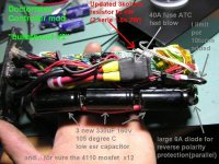
I know that the first time i blown my controller, i installed a 40A fuse inside.. so since i increased the current limit to 75A, maybe with long extended high power demand it blown.. but.. i wasen't lucky... that was not only the fuse... :lol:

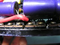
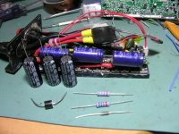
from now, just after i opened the box, i located one visible mosfet that exploded..... i guess that they blow in pair or quad.. so i will replace them.. i have some spare! :wink:

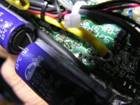
i just hope the IR2101 gate driver did not blown too....

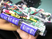
I was surprized to find about 1 ox of sand inside!!!!! :shock: curious, because i completly sealed it!! last time i opened it :|


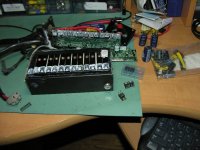
like usual, here are some pics
 

Attachments

  • DSCN4769_800x600.jpg
    DSCN4769_800x600.jpg
    72.3 KB · Views: 7,355
  • DSCN4770_800x600.jpg
    DSCN4770_800x600.jpg
    79.6 KB · Views: 7,356
  • DSCN4771_800x600.jpg
    DSCN4771_800x600.jpg
    88.9 KB · Views: 7,345
again and again...
 

Attachments

  • DSCN4773_800x600.jpg
    DSCN4773_800x600.jpg
    75.9 KB · Views: 7,296
Nice work Doc,
couldn't have done better myself :twisted:

I've seen the screws holding the tabs to the heatsink get loose before. Any chance this happened?
 
fechter said:
Nice work Doc,
couldn't have done better myself :twisted:

I've seen the screws holding the tabs to the heatsink get loose before. Any chance this happened?

All screws had seems to be firmly torqued.. i really think it blow because of the high current that stayed to one phase too much time when i climbed the heavy hill at low speed.. like 1km/h.. it was a REAL HILL! with sand and mud.. so my bike jamed into mud and the motor stoped spining and stayed to one phase too much time.. and they dont like that i think cause the power is normally distributed to 3 phase and not one for long time...

I had chance!! only two fet blown!!! on the negative side so the gate driver and both to-92 transistor that work more for the high side was not affected !!!...

Only two mosfet and one gate resistor :mrgreen:

I replaced them and before to assemble the heatsink and all cover, i tested it and it work!!!


again!!!


I also took time to replaced the red push botton switch that was stick ON for month now..

it is "like new" :wink:

and i stil have in stock 2x 4110, 6x 4710 and 12x IRF3205.. for next blow!! :lol:

but on ebay 4110 are 10$ so... i dont bother with that!

i'll just be less agressive on hill with my ebike!..

Doc

Doc
 
I may be losing it doc ..

but don't the crystalite controllers have 160v 470uf caps?

-steveo
 
no, mine have 160V 220uF.. and some other that i seen on Fechter pics have 220uF too.

some 48V 20A controller have 100V 220uF

Doc
 
See if you can get better capacitors in there. Bigger is not necessarily better, but you want the lowest ESR you can get. ESR is generally lower with a higher capacitance. The quality of the capacitor is very important and it is difficult to get actual specs on them.

If the motor was stalled, you could have a phase current that exceeded the package rating of 70amps each. The legs could melt off before the silicon blows. They can take a lot for a fraction of a second, but if you're going really slow, the current could stay high too long.

If your motor wires had a bit more resistance, they would limit the maximum current to a safe level (at the expense of some loss).
 
fechter said:
If the motor was stalled, you could have a phase current that exceeded the package rating of 70amps each. The legs could melt off before the silicon blows. They can take a lot for a fraction of a second, but if you're going really slow, the current could stay high too long.

You are wrong I'm afraid.
4110 is 180A rated but only at 25'C, At higher temperatures they are lower rated so if your current goes high the temperature goes up even faster as the power loss = I*I*Rds (Rds goes up too) and the same time rating goes down.
So the current rating gone below the temporary current i'm afraid and the legs limit wasn't the issue.

My advice to Doc: try better cooling next time + add some temperature monitoring subsystem.

Best regards
 
Doctorbass said:
fechter said:
Nice work Doc,
couldn't have done better myself :twisted:

I've seen the screws holding the tabs to the heatsink get loose before. Any chance this happened?

All screws had seems to be firmly torqued.. i really think it blow because of the high current that stayed to one phase too much time when i climbed the heavy hill at low speed.. like 1km/h.. it was a REAL HILL! with sand and mud.. so my bike jamed into mud and the motor stoped spining and stayed to one phase too much time.. and they dont like that i think cause the power is normally distributed to 3 phase and not one for long time...

Doc
Of course you know it, but if you stall a 3 phase motor, with the power applied, the amps go through the roof quick. I bet that controller saw hundreds of amps for a few seconds as it went to controller heaven. I agree with Fetcher, I think this is what happened. I don't think even dry ice on the controller would have saved it. :)

( if you do manage to bring it back to life- people will call you Doc Frankenstein )

It only takes a short time to fry a stalled motor without proper protection. My guys did that yesterday when they put a new motor on a locked up gearbox and the starter had incorrect heaters in it. By the time the fuses blew, it was too late as the windings had melted down causing the short. And it was a special 2 speed winding! :evil:

The bad thing about fuses, is they have to take that pesky inrush current and keep on ticking. Some are even "slow blow" e.g. MDL glass fuses, which is no good for fancy electronics IMHO. For this reason, I use a circuit breaker. Inrush current is high as hell. I hope it will protect me...I don't know yet.

In your case, Unfortunately or fortunately, depends on how you look at it - your controller "protected" the motor. I guess since you have some repair parts, you are glad it was the controller. If you didn't toast the winding in the motor, I think you got lucky.

I guess at some point, if people figure out how to "bullet proof" a controller, they will be buying new hub motors now and again. :D
 
why do the control box's have to be so small. couldn't one fab up a box and install a small fan like that is in a sonel charger to keep the heat down
 
diver said:
why do the control box's have to be so small. couldn't one fab up a box and install a small fan like that is in a sonel charger to keep the heat down
Passive cooling is enough for most cases (most loads), but for extreme loads active cooling is necessary i'm sure.
If temperature is dangerously high and still rising the Rds is rising too as it depend on temperature too. As a result you get even more heat and temperature goes up even further. This way thermal runaway starting.

To avoid that, very well forced cooling is necessary IMHO.

Best regards
 
My motor is ok.. like i said, I repaired it yesterday.. few hour after i blown it.. and it work now 8)

My motor still ok ...

guys.. how could you have though that i could be able to blow a X5 !!!! :p it still impossible.. not me.. not anyone did that.. like i know...

I agree that the two mosfet of the phase that stayed ON during few sec have blown because of that.

But.. i still wonder something!!

I mentioned that i had a 40A fuse (a ATC car fuse) so it is a fast blow. and following the specs:http://www.trix.com/Elise-HID/2009.pdf at 75A they normally blow in around 10 sec.

So let suppose that what caused first the blow would be the fuse... like 5 or 10 sec of constant high current demand to 75A... and boom! open circuit!1... ok.. but few milisecond after that, the back EMF of the motor could SHOULD happen and rise the voltage return to several hundread or thousand volts spike noh?

I mean.. put 75A on a few milihenry coils and open the circuit.. you'll get a large HV spike right?

So that situation could had occur about my controller blown when the fuse blew right?..

So that spike would gave follow the neg or pos side source and woudl have zapped the mosfet?

So could it be that fuse blow combined with the inductive spike from the motor that happened?

or you still think that it could be the mosfet thermal limit?


my setup was:
I limit to 75A
Vbatt =65V
Wire lengh between motor and controller 2 ft of 3x 12 AWG
battery volt at 75A: 63V
motor wound resistance: 0.142ohms
4110 mosfet RDS on: 0.0045ohm
stoped to one phase only time estimated 3 sec

The rush current while climbing 75A during 7-8 sec

ATC 40A fuse blow in:
100sec at 55A,
10 sec at 75A, and
2 sec at 100A

so one phase activated at 65V give a phase current of:

65V - 3Vdrop = 62V
62V / ((2s2p 4110 mosfet) + (2x 2ft of AWG12) + (2x 4ft of AWG 10) + (r of switch contactor) + (r phase)) = current to one phase

62V / (0.0045ohm + 0.006ohm + 0.008ohm + 0.01ohm + 0.142ohm) = I

62V / 0.170ohm = 363A !!!!

two parallel 4110 mosfet of one phase can handle max 180A each at 25 degreeC = 360A for both parallel

hummm 360A vs 363A... strange coincidence!!! :?

Doc
 
Ok.. so now some pics of the update for re-bulletproofing V2 my controller !

Doc
 

Attachments

  • summary  of repair.JPG
    summary of repair.JPG
    103.1 KB · Views: 6,705
  • DSCN4779_800x600.jpg
    DSCN4779_800x600.jpg
    89.1 KB · Views: 6,900
Doctorbass said:
hummm 360A vs 363A... strange coincidence!!! :?

Doc

It is only coincidence.
Sorry Doc but yours calculations are wrong. You should keep in mind than one phase is activated at several PWM cycles. At each PWM cycle current goes from capacitor to motor and back again from motor/coil to capacitor.
If your current at battery side is limited to 75A at 63V, so i suppose at motor side the current is limited to ~180 A (it depend on total resistance at coil/motor side).

Best regards
 
eP said:
Sorry Doc but yours calculations are wrong. You should keep in mind than one phase is activated at several PWM cycles. At each PWM cycle current goes from capacitor to motor and back again from motor/coil to capacitor.

I don't know about xlyte controllers but most RC controller stop PWM at full throttle and just commute the phases (measured with a scope on a CC ESC). It raises efficiency in full throttle operation by reducing switching losses. So Doc's calcs are not unfeasible.
 
curious said:
I don't know about xlyte controllers but most RC controller stop PWM at full throttle and just commute the phases (measured with a scope on a CC ESC).

It is valid for all 6-step controllers at FULL throttle.
 
curious said:
eP said:
Sorry Doc but yours calculations are wrong. You should keep in mind than one phase is activated at several PWM cycles. At each PWM cycle current goes from capacitor to motor and back again from motor/coil to capacitor.

I don't know about xlyte controllers but most RC controller stop PWM at full throttle and just commute the phases (measured with a scope on a CC ESC). It raises efficiency in full throttle operation by reducing switching losses. So Doc's calcs are not unfeasible.

For RC controller stopping PWM makes sense as at full throttle phases are comutted at high freq. which is close to PWM freq (it depend on Kv and voltage).

But for heavy loaded motor (which is next to stall) it have no sense anymore.

But if i'm wrong and this is true for Doc's case, so could anybody explain how current limit work in such case (when PWM is absent) ?

Best regards
 
Bingo. IIRC, the current limit is manifest by throttle pull-down (pwm).

:?
 
guys.. how could you have though that i could be able to blow a X5 !!!! :p it still impossible.. not me.. not anyone did that.. like i know...

I bet you could blow an X5 if you had a 50KW controller for it. :p
 
Hi there,

by looking at the pics, I think the heat transfer from the IRF to the aluminium strips may not be adequate.

From reading the IRFB4110 data sheets, 75A should be a negligible current if distributed over 2 devices. This should give about 20 Watts of heating power only. However if heat cannot flow from the package fast enough, you blow'em up.

I would suggest, that instead of mounting them isolated on aluminium, it would be better if you'd replace the alu-strips with copper strips, and solder the Mosfets directly to the copper strips, which in turn are mounted isolated from the main heat sink. Then you have an immediated heat transfer from the package to the copper.

Your blow-up is really interesting for me, as I intend to use the same Mosfet device for my Quantya bike, which needs much more current. I'll try soldering them directly on CUPONAL strips. Those are copper on the outside with an aluminium core. This would give you a current terminal and heat-sinking at the same time:
http://www.sps-standard.com/verbundschiene-cual.0.html?&L=4

Just out of interest:
If anyone has the crystalite schematic, I'll be glad to take a peek at it ...

Fun,

Charles :)
 
were you at low throttle when it blew?, if the battery current limit is 75A at low throttle the motor current can be much higher, at 50% PWM motor current will be double the battery current. so if you were at like 25% PWM and the battery current was 75A the motor current would be 300A, there must be a mod you can do to these controllers to limit motor current instead of battery current. but still, its a 6 step commutation so at any one time only 4 of the 12 mosfets will be conducting so they only see an average current of 33% of the motor current, i don't know if that controller uses only the body diodes in the fets as the freewheel diodes, but if it uses additional diodes to lower losses they will see even less than 33% of the motor current. how many mph were you going when they blew?

ok i saw you said 1km/h, on a 24" wheel thats 8.6 rpm, how many poles 16? of so thats a commutation frequency of 1.15Hz, or each commutation step lasting 0.14 seconds, thats not very long, is 300A for 0.14 seconds through 2 4110s in parallel enough to fry them? im not too sure about the amps though, id have to consider think about it more considering the motors resistance and stuff to figure out exactly what PWM duty cycle the controller would be running in that situation where the battery limit is 75A.
 
dirty_d said:
its a 6 step commutation so at any one time only 4 of the 12 mosfets will be conducting so they only see an average current of 33% of the motor current,
Wouldn't they see 100% motor current 33% of the time?

:?
 
dirty_d said:
were you at low throttle when it blew?, if the battery current limit is 75A at low throttle the motor current can be much higher, at 50% PWM motor current will be double the battery current. so if you were at like 25% PWM and the battery current was 75A the motor current would be 300A,
[cut]
ok i saw you said 1km/h, on a 24" wheel thats 8.6 rpm, how many poles 16? of so thats a commutation frequency of 1.15Hz, or each commutation step lasting 0.14 seconds, thats not very long, is 300A for 0.14 seconds through 2 4110s in parallel enough to fry them? im not too sure about the amps though, id have to consider think about it more considering the motors resistance and stuff to figure out exactly what PWM duty cycle the controller would be running in that situation where the battery limit is 75A.

Once again:

my setup was:
I limit to 75A
Vbatt =65V
Wire lengh between motor and controller 2 ft of 3x 12 AWG
battery volt at 75A: 63V
motor wound resistance: 0.142ohms
4110 mosfet RDS on: 0.0045ohm
stoped to one phase only time estimated 3 sec

Is 300A current possible at 25% duty for above params ???
 
Back
Top