How? Cycle Analyst to Crystalyte Cntrller to limit current?

steppedup

1 mW
Joined
Nov 22, 2007
Messages
10
Hi all,

Sorry for the newbish questions - does anyone know where I can find any step by step instructions for on how to actually wire up the Stand Alone Cycle Analyst so that I can use its advanced current limiting functions?

I've blown out 3 Dewalt 36 volt batteries so far. But....I'm getting tired of disassembling them and recharging individual cells.

So, want to get the Stand-Alone Cycle Analyst working to its full capabilities and limit the current.

My SA CA is currently hooked up to a 72 volt, 35 amp controller like this one here: http://www.poweridestore.com/35A36V-72V-X-5-Motor-Controller

I followed these instructions to hook it up in basic mode and it works just fine:
http://www.ebikes.ca/drainbrain.shtml (step 7)

I have seen these instructions:
http://visforvoltage.org/forum/2619-cycle-analyst-used-control-and-extending-range

Which I'm a little concerned about following - even the more spelled out directions if you scroll down.

Here are the orginal instructions for how to take advantage of the current limit - if someone can hook me up with pictures showing step by step on how to do this?

Throttle Over-Ride Details

In order to take advantage of the speed limit, current limit, and low voltage cutout, the Cycle Analyst needs to be wired in such a way that the throttle-override output is able to take charge of the motor controller when one of the limits is surpassed. The output is a stiff analog voltage that can range from 5V down to 0V. When it detects that a limit is exceeded, the voltage begins to ramp down from its resting point (set by ItermMax), until power to the motor is reduced and the limit (speed, current, or voltage) is no longer exceeded.

By comparison, the user typically has a throttle signal that varies from close to 0 or 1V when it is off, up to 4-5 V when the throttle is fully engaged. For proper operation, the signal for the motor controller should be the lower of these two voltages. An easy way to achieve this is with a diode and current limiting resistor on the throttle line as shown in the following schematic:
 
another "newbie" tries to explain :

i have just the same setup (controller and CA).

I opened the CA
inside you will see the soldering pads where the wires from the shunt and the speed sensors are connected.
There you will find an empty pad marked "Th" (left side second from bottom)
http://www.endless-sphere.com/forums/download/file.php?id=7507
you connect a wire here and get it out of the CA box.
This wire you connect to the throttle signal line (usually green).
Since this throttle signal is available on many of the connections of the controller (break switch, throttle, cruise control, pedal assist) it does not matter where you connect it, i used the break switch, but you also can solder it directly to the controller throttle point.
The CA throttle override just pulls the throttle signal more or less against ground (it cannot enforce higher throttle values than set with the throttle handle)
The reason for the resistor and the diode is just to protect the CA against too high current, which (as Justin confirmed) is not really necessary in most cases with recent controllers.

Once again : you can manually simulate the function of the CA by shortening the green (throttle) wire against GND and the motor will stop.

Next is to adjust the settings within the advanced settings parameters of the CA.
For me the default settings where just fine and worked nicely.
Unfortunately i do not have the parameters at hand, but could read them out and send it to you.


Try it, it will work!
Good luck
 
Thanks a million for the picture of the CA - definitely see what you mean there!

I feel really, really dumb for asking this, but when you said,

"Since this throttle signal is available on many of the connections of the controller (break switch, throttle, cruise control, pedal assist) it does not matter where you connect it, i used the break switch, but you also can solder it directly to the controller throttle point."

Do you have a picture of where you connected it? Or how do I tell where the controller throttle point is? Or where the break switch is?

Have you planned how you're going to waterproof the line out from the CA? (No worries if not - I'm on the Olympic Peninsula, so am trying to reduce my risk factor there).
 
Nuts, check here for a bit of direction on the serial link http://www.endless-sphere.com/forums/viewtopic.php?f=4&t=3466

Steppedup, what controller are you using, or planning on using ?
 
re water resistance

be carefull the CA is not waterproof !
I applied plenty of silicone and hotmelt glue but i am not sure ... anyhow i am not planning any real diving adventures with my trike tandem!

re serial communication CA
It would be nice to motivate Justin to provide an ISP programming option to upgrade the firmware of The CA

I am still pending between making a hardware interface and programming CA functions on my pocket PC or for my ordered new Iphone, or using the CA (provided i can make it communicate) as an interface to other devices.
Imagine to use Apple´s Iphone as a universal Bike computer, showing on the nice display Amps, Speeds, Watts, Battery status etc. playing music or videos for onboard entertainement, routing and tracking using Goggle Maps .... a bike hiker´s heaven !
 
I'm using this 72 volt, 35 amp controller:

http://www.poweridestore.com/35A36V-72V-X-5-Motor-Controller
 
Have you had a look over the CA's webpage yet ?
It has info and pictures on wiring up the throttle hookup

http://ebike.ca/drainbrain.shtml
 
Yep - but I don't know how to hook up the diode, etc...

So I'm going to go for the simple version....

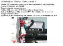
Do I cut the red cable or the green cable?

The original link says to use the red cable:
http://visforvoltage.org/forum/2619-cycle-analyst-used-control-and-extending-range
(for your convenience - here's the specific section: http://www.endless-sphere.com/forums/download/file.php?mode=view&id=10751)

But hejo's update says to use the green wire:

http://www.endless-sphere.com/forums/posting.php?mode=reply&f=2&t=4865#pr72080
(for your convenience: "This wire you connect to the throttle signal line (usually green).")
 

Attachments

  • throttle is red.JPG
    throttle is red.JPG
    28.9 KB · Views: 2,957
Justin´s (the developer of the CA) intention was to put the CA into the throttle signal (usually green) between the exit of the throttle and the controller.
He must have had reasons to do this.

The approach from usatracy in visfor... is different. He feeds the 5V supply (red line from the controller) into the CA.
Only the experts here and possibly Just could explain / approve this method.

I could imagine that this could cause an overload on the CA, but i dont know.
 
I just wanted to bump this thread as I am about to wire my stand alone CA to my e crazyman controller so I can limit the amps and speed. Befor I go ahead with it I have some questions.

From my understand the CA just grounds the 5v throttle output to shut the controller down when a max amp/speed value is reached?

Most controllers have a throttle signal that starts of at 0v and ends at 5v - full throttle but the CA needs a signal 1-4v?

I just tested my throttle feed to the controller at 0% throttle it's .77v and 100% throttle is 4.80v is this ok to just wire it in ?
 
I just opend up my CA and solderd one extra wire to the throttle over ride pad and ran this down to my blue/green throttle signal wire .turned the bike on and as soon as CA booted up 60kg of bike and trailer shot off and knocked me over.

I did some more digging around to find out the throttle override will output about 5v until it the override kicks in. I now realise why you need that diode :( well at least I am slowly getting there.

I am under the impression that you can use any old diode? some of my options are
http://search.dse.com.au/search?w=diode&sessionid=48e60a8f0fda37202740c0a87e0106a2&ts=new
kurt
 
Kurt said:
I am under the impression that you can use any old diode? some of my options are
http://search.dse.com.au/search?w=diode&sessionid=48e60a8f0fda37202740c0a87e0106a2&ts=new
kurt

Hi Kurt, yes you can use any old diode. It is only handling under a milliamp of current.

As for the way in connecting the Th pad, you should indeed do it to the throttle signal line as I described rather than using the Th pad as the 5V power bus to the throttle. SInce early 2008, all of the CycleAnalyst boards have a current limiting resistor on the Th output so that when people accidentally connect things the wrong way they are less likely to fry the circuitboard. This resistor will limit the output so that the Th pad won't be able to power up a hall throttle (which usually requires about 5mA).

Justin
 
I got a diode today ,After doing some testing first with a multimeter I can see that there is a voltage output from the new Th pad wire of around 3.8v and when the max amp draw i set is exceeded this voltage ramps down to 0v .I can kinda see how this would work if it were suplying the voltage to the throttle but intersecting the signal back from the throttle I am not sure how and wouldn't the diode stop any voltage at all getting through?

perhaps I am just making a simple thing complex or I am missing something in my interpretation of how to tap this over ride in.

I have posted a pic of my 3 wire throttle cable and labeld them . I have a single wire in my hand coming from the Th pad of the CA and a diode were do they both fit in this picture? Sorry for my incompetence I am usually not bad at this kind of thing :?

2911249566_e041e5a3a7.jpg
 
I have my new wire and inline diode running form the CA Th pad running down and tapping into the blue wire that is the return signal from the throttle to the controller . In operation It dosn't seem to be limiting the current at all

Now from my understanding this inline diode is stopping the 5v or there about's that is active on the CA Th pad from running down my new wire and entering the throttle return signal and making my bike take off.

Perhaps I am just silly but how is the CA ment to control the throttle signal now that there is a diode there stopping any voltage getting through. its alowing voltage back up the wire to the Th pad but just cant get my head around how with one wire the CA can override the throttle return signal but still allow it to function as normal until your max amp /speed are reached. Am I missing something in having just one new wire coming from the CA Th pad ?

I am trying to make this work on a brushed speed controller.

Kurt
 
Kurt said:
I have my new wire and inline diode running form the CA Th pad running down and tapping into the blue wire that is the return signal from the throttle to the controller . In operation It dosn't seem to be limiting the current at all

Hi Kurt, it won't work if you don't have something to limit the current that the throttle will try to source, that's why there is a resistor in the schematic that is suggested. A throttle that is ON will sink about 60mA if you short the output signal to ground, so you need to reduce this with a ~4K or so resistor, exactly as shown in the schematic.


Perhaps I am just silly but how is the CA ment to control the throttle signal now that there is a diode there stopping any voltage getting through.

What you want is for the CA only to be able to pull a high throttle signal low, you don't want it to be able to drive a low throttle signal high. The diode is one wonderfully simple way to achieve this.

-Justin
 
The approach from usatracy in visfor... is different. He feeds the 5V supply (red line from the controller) into the CA.
Only the experts here and possibly Just could explain / approve this method.

I could imagine that this could cause an overload on the CA, but i dont know.

I first did this back in mid 2007, that Cycle Analyst is still on the bike, has been through 4 motor controller conversions and various battery chanegouts and now is on lithium.

We have never had a problem with the CA unit being wired this way and actually forget it is there when we redesign and retool the bike, it just works.

We have provided CA units to customers and have wired them in this same weird backwards way, as Justin says, there now is a resistor that prevents you from wiring in this fashion.

My recommendation would be to follow Justins way of wiring to the throttle and not to attempt my weird backwards way, I just wanted to clarify that there has been no problem with mine or others that have been wired in this reverse fashion where the CA powers the throttle hal and thereby controls the amps and speed, but I think Justins method is better in the long run, for you and him :)
 
The way usatracy did it essentially powers the throttle from the CA instead of from the controller. When the CA output goes low, the throttle supply voltage drops to zero and so does the output. At in-between voltages, the output is roughly ratiometric, so this should work fine.
 
Sorry, bumping this one up again for a few quick questions...

I have the CA stand-alone and a 500W Cyclone Kit w/throttle. The throttle cable is a small black ribbon with 5 or 6 wires in it (throttle also has battery meter). What's the easiest way to identify the throttle signal wire?

Also, I understand the schematic, but I don't know that much about diodes and the CA info doesn't state anything other than calling it a diode. Is there a particular rating that I should look for (amps or volts)?? Aren't diodes rated per voltage or is that transistors? I found a site I'm ordering some stuff from and I saw a bunch of different diodes, how do I know which diode to get?

EDIT: The kit also comes with switching brake levers, should I just use one of the wires from the brake lever? I think someone said that is also the throttle signal wire.
 
The diode can be almost anything. a 1N914, 1N4148 or 1N4001 will work.

I don't know the pinout for a Cyclone throttle, but if you can measure the voltage on the wires (against battery neg.), it will be the only one that changes when you move the throttle.
 
Welcome to that club! I failed with my first two attempts to wire things correctly finally, giving up even with new (simplified)instructions. I wish that wasn't the case because my system routinely drew 40 amps and sometimes 50. Now my balancing charger is toast and the point is moot.
Aside: Anybody know where to find a 36V balancing charger and how to splice my old plug to the 12 cells?
 
Back
Top