You may already know a few of these things.
1. I would recommend Kiwi drop out adaptors. You might have to grind down a corner of the adaptor (15min of work) but other than that they just bolt on to the existing drop out.
Got em, love em
http://endless-sphere.com/forums/viewtopic.php?f=6&t=33767
2. To fit a cromotor you will need a 150 mm swing arm especially if using kiwi drop outs.
To get one you can buy a 2005 frame off of pink bike (online used bike website) and the drop out inside width should be 150mm. Make sure you ask for the width. If they say yes ask for a picture with a ruler showing the width so you don’t get cheated like I did. Here is one frame for $300. I paid $270 for my second frame but mine did not come with a rear shock and I need a new one.
http://www.pinkbike.com/buysell/1437412/
I'm going to try my 135mm swing arm first. I know some have gone with the 150mm but others have done it with the normal frame. I'm not ruling it out but with my preliminary measurements and some careful, gentle widening of the rear drop outs I got it out to 145mm with very little effort or stress on the components. It moved right back to the original width when I was done.
3. Make sure you order extra c washers for 4 or 5 total to make room for the wiring coming out of the cromotor.
I actually make my own with nice polished mouths as escapement so for the wires. Careful, careful.
4. Make sure your disk brake does not touch the wires coming out of the motor. It will easily slice right though them.
Got a lesson in this on my first build. Won't soon forget it.
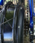
5. I’m not sure how much but you should order shorter spokes for the left side of the rim. My cromotor is NOT dished and my tire (Maxxis Hookworm) has 1mm of clearance on the right side of the swing arm.
Been measuring this detail the last couple of days. Check this earlier thread by me regarding the Giant off-set and the amount of dish necessary to center up the wheel:
http://endless-sphere.com/forums/viewtopic.php?f=2&t=55577
I was pulling my hair out until I realized that 1mm of dish removes 2mm of off-set.
6. I don’t think anything more than a 1 speed free wheel will fit on the back (motor) unless you stretch your swing arm a lot.
Got this three speed Como freewheel off amazon. It's 16/19/22 and actually feels pretty good and tight. The quality might not be the greatest but neither was the 11 tooth 7 speed I put on my first build and it has been golden. I threaded it on the motor and it fits within the axel shoulder so.... I'm gonna try it and see what I can do.
We both have similar bikes I’m just using a 24 fet controller and 6s 8000mAh Turnigys instead of Zippys. At first I was going to go with Zippys then I changed my mind. I wish my bike was kept blue like yours I really like the color (some owner before me painted it black). I would be interested to see more pictures of the rack your batteries are sitting on and how close the controller bolts come to the batteries.
The bolts are carriage bolts and the shallow rounded head sit in the bottom of the battery tray. I also counter bored where they sit in the tray so that they are inset into the aluminum a bit (one of the benefits of this thicker material) A 1/4" piece of high density closed-cell foam sits on the bottom of the tray with circles cut out over each bolt head. Then another 1/4" layer of foam sits on top of that. The batteries are wrapped in several layers of the same foam in a thinner gauge. It fits very snugly into the bottom tray. The tray itself is 5" wide architectural aluminum channel (6063 with sharp corners inside and out) with 2" legs and 3/16" wall thickness. It's softer than some of the other extrusions since it is not generally meant to be structural but with that wall thickness it's plenty stout for this application. I shortened the legs to 1". The torsion rods between the tray and the controller bracket are just some thick walled aluminum tubing. The torsion bolts (carriage bolts with the square part passing through the bottom of the battery try) go all the way through the controller bracket and secured with whizz nuts.
Also I am curious to why you chose to mount your controller with the wires facing to the front of the bike?
I make a snap-on cover that goes over the whole controller and the wiring bundle. See:
http://endless-sphere.com/forums/viewtopic.php?f=2&t=46942&start=100
I just think it looks better this way with the cover on it.
Looking forward to see your finished battery box.
Got some work done on it over the last couple days. Embedding the wiring harnesses in the foam etc. took pictures and will post them soon.