C-SMD1.2 Controller pad functions, Regen, etc. XC8M06 based

amberwolf

Administrator
Staff member
Joined
Aug 17, 2009
Messages
40,842
Location
Phoenix, AZ, USA, Earth, Sol, Local Bubble, Orion
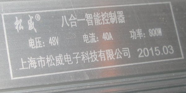
This controller was sent to me via Dogman, to run my new trike the SB Cruiser. It's purportedly a 40A controller, but even after I figured out the 3speed switch and other stuff, it still gets a peak of 33A max (on one ride it once got a peak of 40A+ but I have no idea why and it hasn't happened again). Basically that means the SB Cruiser doesn't have enough power to get out of it's own way, much less accelerate in traffic at any safe rate.


I've got an X5304 on the front in a 26" wheel, so I have the possibility for quite a bit of startup power, if I can get the controller to feed it to it from the "48V" EM3EV A123 20Ah prismatic pack.


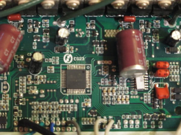
It also doesn't seem to have regen enabled yet, though I haven't played around with the pads yet.

I did find some pics of a similar controller elsewhere on ES, but there wasn't any further info about it in the threads I could find it in, as far as pad connections and whatnot go.

Anyone that has had one of these and gotten regen working, I'd appreciate knowing what pads to hook up, before I experiment with it and probably blow it up (leaving the SB Cruiser with only a 25A controller at that point...which also doesn't have regen).


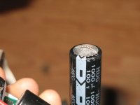
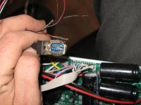
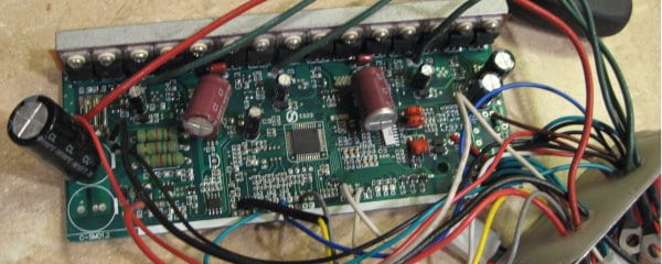
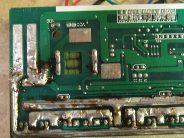
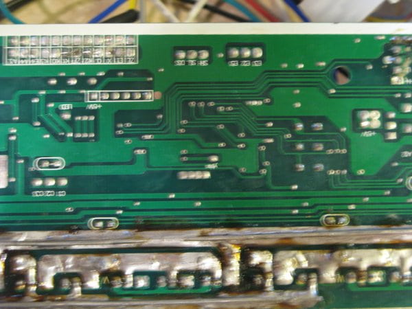
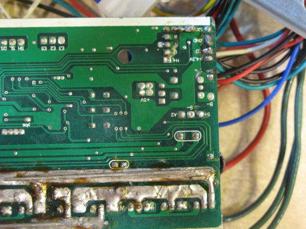
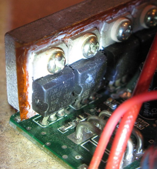
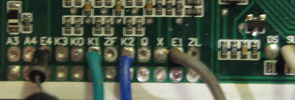
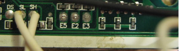
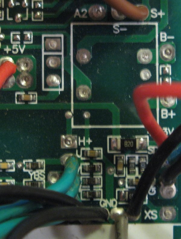
Some of the controller pics from the SB Cruiser thread:
http://www.endless-sphere.com/forums/viewtopic.php?f=2&t=67833&start=50#p1028407

file.php


file.php


file.php


file.php


file.php


file.php


file.php


file.php


file.php


file.php


file.php


file.php


The SB Cruiser itself as it should look once paint and panels are done:
file.php


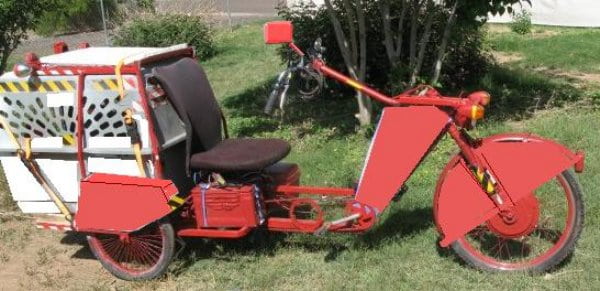
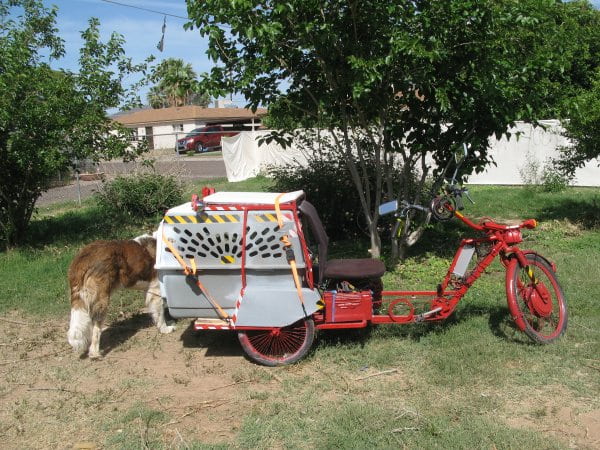
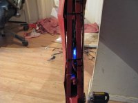
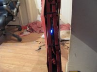
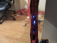
and as it is right now:
file.php
 
I got the 40A again for one acceleration today, with either 33A or less the rest of the time (felt like a LOT less, maybe half) when I took Tiny up to work to socialize and meet people/dogs/etc.

After it happened (about halfway up there) and then went away, I played iwth the 3speed switch and got no change in any of the three results at first, which is strange. Usually the farthest forward position gives me low power mode, and the middle and back positions give me the same medium power mode.


I have a feeling there is an intermittently broken wire inside the center-ground on that cable, inside the insulation, or a really bad solder joint at the board. Could be the switch itself, too, but that's less likely in my experience with wires vs switches, especially on cheap ebike stuff.

I had planned to also take the controller back apart and experiment with it today, but did not get to.

So I'm still looking for any info others have on this type of controller, pertaining to regen, current limits/speed modes, etc.
 
whats the serial number on the board ( cant read it on the pics)? do you know which company dogman got it from?
Maybe check the greentime controller thread, see if its same board.
 
I don't remember if ti has a serial number, though there is a sticker on one of the chips if that's it. Have to check and get pics.


I did read all the stuff I could find on the greentime ones, as it seems to be similar, maybe even the same, but didnt' see anything listing the pad functions. Some said what wire colors/connectors did certain things, but mine doesn't have the same colors/etc, and none of the connectors on mine enabled regen or affected current/power ability (other than one setting of the 3speed switch making it *less* power).

I could've missed something, which is part of why I made this thread, in hopes someone with that info might see it and let me know. :)


If not, eventually I will take the controller apart again and experiment with it, but given my track record of blowing stuff up doing this, I'd hoped to avoid that.... :p
 
one pic you posted earlier shows the serial number on the board, but I cant read it ( its blurry )
it will assist in finding same brand
x.jpg
If can work out which brand it is, might be able to find more info
looks like G -SMO1.2 but not sure, if can find a board with SMO on it, likely it will be same brand.
 
Ah, that's the "C-SMD1.2" that is in the title of the thread. ;)

It has the same thing in the silkscreen on the opposite side of the PCB on the same corner.
 
whoops! I did some searching, seems alot of electronic devices use smd in the serial on the board , couldn't find anything relating to ebike controllers, if I find one I shall post.
 
I appreciate it. I did quite a lot of googling around on ES and off, and found various pics that look like this type of controller, but no information on what the PCB pads do.
 
I have a greentime controller which has serial number in same format:
c-smb2.3 its not same controller but I would guess the controller you have is from greentime.
with that in mind I opened up my controller ( 36v/48v 30amp 800w), going from one of the greentime wiring pinouts on greentime thread it looks like regen braking is the orange wires, one wire goes to E1 and the other to ground
I've left the controller open in case you want any other pin info.

View attachment 2

csmb23 back.jpg

pic below shows the two orange wire pins ( note there is another orange wire going to k1 but its for speed level).

csmb23 regen.jpg
 
Thanks!

That looks liek the same basic contorller, so as long as mine doesn't have different firmware or settings, your wiring ought to do the same thing on mine.

It does look like yours says C-SMD (not SMB) so I guess the version is just older on mine?
EDIT: I zoomed in on your pic and you're rigth, it says SMB not SMD. :oops:


Is yours also a 15FET? If so, then I guess the 30A (rather than 40A mine is labelled for) I get almost always as max makes sense. Was hoping for the 40A it says it can do....


I'll be doing work on the trike this week (tonight probably) for vacation, so I'll letcha know asap if I need other pics or info.

But any info you can give as to which pads go to which functions / outputs / inputs on yours could be helpful. they may not match mine, but they will at least help me figure out which things *could* do what, if mine did them. :)
 
Its a fairly new controller, on the controller it says april 2014, I think yours is newer model. Just looking at your pics compared to mine, its same board pretty much, what a stroke of luck!
I will post more pics of wiring as soon as I get a chance. Its 12 fet 36/48v 30amp 750/800w, is whats on the outside sticker.
Maybe the serial number difference is something to do with the 12 or 15 fets version, but the outline of the components looks pretty much identical ( i.e. how the board is laid out, marked pins etc).
 
to amberwolf: your ocntroller only has sensorless wires connected? ( no hall sensor wires?)
a few more connections:
XZ : two white wires with connector: select voltage both white wires connect at XZ, two holes under it ( located bottom left of board)

braking: SL brake low ( stop low I guess): white
SH brake high ( stop high I guess): yellow

DS in my controller this is connected by internal white wire to X , it maybe necessary for this connection for regen braking to work via brake handle instead of cut off controller power when brake activated but i'm not sure on that.

E1 and E1 gnd ( directly below E1), I think this is to turn on or off regen braking function ( which is activated when riding via brake handles.......thats my guess!)

VCC :purple wires: one is power on/off to thick red main wire to batt, another purple wire to measure battery voltage,
both connect to VCC on board....i.e. battery voltage

k1 k2 : speed select: orange k1 blue k2

Q : cruise control: pink wire

more later
other threads related to greentime controller boards: followed some links and seems hua tong may have been forerunner of greentime, not sure if its same company but seems same controller ( a few years back anyhow)
http://endless-sphere.com/forums/viewtopic.php?f=30&t=33636&hilit=greentime&start=25
http://endless-sphere.com/forums/viewtopic.php?f=2&t=29469&start=465
http://endless-sphere.com/forums/viewtopic.php?f=2&t=31946
 
whatever said:
to amberwolf: your ocntroller only has sensorless wires connected? ( no hall sensor wires?)
Unfortunately this one cant' do sensorless, AFAICT. Halls are the 3 all green wires over near the corner of the board with throttle/etc. (phases are all green, too--I guess they figure with autolearn it doesn't matter what colors they are?)

EDIT: I was wrong about this: It actually can't do *sensored*, despite having hall wires, it does not bother to read them; operation is identical with or without them attached, under all conditions. :(


Thanks for the below. I've also posted my test results from last night (in the next post). I didn't try hooking pads to each other (just 5V or ground), so I'll have to try the part in bold.


a few more connections:
XZ : two white wires with connector: select voltage both white wires connect at XZ, two holes under it ( located bottom left of board)

braking: SL brake low ( stop low I guess): white
SH brake high ( stop high I guess): yellow

DS in my controller this is connected by internal white wire to X , it maybe necessary for this connection for regen braking to work via brake handle instead of cut off controller power when brake activated but i'm not sure on that.

E1 and E1 gnd ( directly below E1), I think this is to turn on or off regen braking function ( which is activated when riding via brake handles.......thats my guess!)

VCC :purple wires: one is power on/off to thick red main wire to batt, another purple wire to measure battery voltage,
both connect to VCC on board....i.e. battery voltage

k1 k2 : speed select: orange k1 blue k2

Q : cruise control: pink wire


other threads related to greentime controller boards: followed some links and seems hua tong may have been forerunner of greentime, not sure if its same company but seems same controller ( a few years back anyhow)
http://endless-sphere.com/forums/viewtopic.php?f=30&t=33636&hilit=greentime&start=25
http://endless-sphere.com/forums/viewtopic.php?f=2&t=29469&start=465
http://endless-sphere.com/forums/viewtopic.php?f=2&t=31946

Thanks--I had not seen the last one, but I did find the first two--just didnt' see the actual pad info in there (did find some wire info but it didn't match my connectors/wires, from what I could see).

EDIT: I like this line in the translation of a chinese document:
8. There is sufficient room for expansion of functions, because the microcontroller's program space, IO ports will be more, so we can party
:lol:
 
FWIW, there's a chip on mine (not the MCU) that has a paper lable with "125.6" on it, as far as I can read it. Dunno what's under the label.

Ok, now since I can't get good nonblurry pics for some reason, and uploading takes forever on the wifi's I've found, then for pad definitions, I'll just make a list of what mine are, and the wire colors I happen to have attached to them right now.

note that I have extra pads A3 and A4 that yours doesn't

Mine (C-SMD1.2):
(where known I have used ** for your pad functions vs mine)

A3 4,83v ?active wheel lock? active low
A4 0v ?active wheel lock? active high
E4 reverse (anode diode yellow) active low
**E4 (reverse)
K3 5v ?no effect?
K0 5v grounding pulsed toggles between speed modes, regardless of 3speed switch setting.
K1 3speed switch (green)
**K1 (3speed switch)
ZF ?output? is 5V when speed mode is low or med, is 3v when high
K2 3speed switch (blue )
**K2 (3speed switch)
Q ?output? is 3V when speed mode is low, is 5v when med or high
**Q (cruise)
X 5v ?active wheel lock? active low When tied to DS, causes regen/wheel lock during braking
E1 self learn (gray)
**E1 regen (active low)
ZL 5v ?no effect?

DS 5v ?brake cutoff? (not regen) goes to 0.54v when sl=gnd When tied to X, causes regen/wheel lock during braking

SL Ebrake cutoff (White) (active low)
SH ?no effect? (white)

?speed mode indicator outputs? when 050 is med or high, when 550 is low
E5 0v
E2 5 v
E3 0v

YBS ?output? matches V hall signal?
H+ Hall power (no wire)
U U hall input (green)
V V hall input (green)
W W hall input (green)
GND (x5) Main signal grounds (gray from autolearn) (black from ebrake) (black from Hall ) (black from 3speed switch) (black from reverse)

+4.3V Throttle power (red)
SD Throttle input (green)
GND Throttle Ground (black)

XS ??matches throttle input signal?

+5v (x4) Hall Power (red)

A2 ?output? 0v normally goes to 5v when ebrake engaged
S- ?inverted S+?
S+ Analog output of one phase signal. (brown)

C1 Output Speed setting indicator Low
C2 Output Speed setting indicator Med
C3 Output Speed setting indicator High
(can put LEDs anode to Cx and cathode to ground, used 33k resistor during test as was handy, may not need one)

Are also some pads for B+ and B- on an unused relay outline; suspect they are for turning a brake light on and off, since the A pad above them goes to 5V when brake is engaged, but all the drive circuitry is not present for the relay either.


LED on PCB (and LED pad) Blink codes:
hearbeat 1hz = normal
2blink 1hz = ebrake on, same for wheel lock
no blink = motor running
(external LED can be added via LED pad)
 
whatever said:
Its a fairly new controller, on the controller it says april 2014, I think yours is newer model. Just looking at your pics compared to mine, its same board pretty much, what a stroke of luck!
I will post more pics of wiring as soon as I get a chance. Its 12 fet 36/48v 30amp 750/800w, is whats on the outside sticker.
Maybe the serial number difference is something to do with the 12 or 15 fets version, but the outline of the components looks pretty much identical ( i.e. how the board is laid out, marked pins etc).

Kinda like how the "infineon" and "xie chang" boards look the same (for a particular revision) regardless of number of FETs, for the most part?

Definitely a stroke of luck, especially in that you're willing to help out and take the pics and stuff. :) Which I appreciate a lot--it's already probably solved the regen thing, because of the DS to X link.

I think that works because X appears (on mine) to be an active wheel lock, when grounded. And DS is an *output* pin for the braking detection, AFAICT, which goes low when the brake is applied. So DS hooked to X will engage the active wheel lock *only* when braking occurs. Which makes sense for your setup there.

(the only possible gotcha is that on yours, the E1 pad for regen activation is self-learn on mine)

It's "more" than just regen: off-ground I found last night that if the X pad is grounded while at any nonzero throttle level it'll stop the wheel and there is current flow back to the battery for an instant, before it actually stops the wheel. Then it *holds* the wheel lightly in place, actively fighting me turning it by hand. It isnt' a very *hard* fight, and I could probably have pedalled against it when I was younger, might even be able to do so now in a really low gear, but it's not just a typical regen brake.

There's also two other pads on mine (A3 and A4) that also activate a wheel lock, one if it's high and one if it's low,
 
Reading thru that last link
http://endless-sphere.com/forums/viewtopic.php?f=2&t=31946
it's definitely the same type of controller as this one, and it has even more info on it than I had ever hoped to find, so THANK YOU!

:D


I actually remember reading that thread at some point, perhaps when it was originally posted? Not sure. :?


The descriptions are pretty detailed, even if they are an automated translation of some type, and a little mixed up here and there. The abbreviations in the description for pads are not the same as on the PCB, but I suspect they are still teh same one.


This section:
3 less than the battery voltage automatically drop streaming technology, when the battery voltage is less powerless to undervoltage protection, if sustained high current output, Battery internal resistance will lead immediately into the under-voltage protection controller, and battery but it is still electricity. In view of this situation, Our controller in the battery voltage less than 44V, current limit value will decrease as the battery voltage decreases, the controller Small current form can continue to run, to effectively improve the electric vehicle to continue the mileage. When the battery voltage is less than the undervoltage protection
Protection point, the shutdown output, protecting the battery.
leads me to believe that perhaps the reason I'm not getting full 40A out of this is that my A123 pack's voltage isnt' as high as it expects it to be, even at full charge, so maybe it's turning down the current for that reason? I can't remember the conditions under which I have gotten 40A, but I think it had been hot off teh charger each time. Gonna have to test this theory using one of the other packs that has a little higher starting voltage.


This section:
First self-learning lines (LEARN) ground, and then open the electric door lock, turn the motor a few steps, when the motor stops rotating, and failure means Lamp (ErrLed) no flash nine under, that automatic identification has been successful. At this point turn to be able to turn the motor increases, the re-release the switch Added switch to switch the direction of motor rotation can be. Identification is successful, the self-learning lines and broken ground, and then turn off the power door locks.
(Note: Since the motor is in the learning process should be carried out under no-load situation).
probably means that when using the self-learn you wait till it flashes the LED 9 times and stops the motor, and then it's done. When I used the function before I had the case on so couldn't see the LED. I think I'm gonna wire up an external LED sticking thru the wire bundle holes so I can see what it's telling me if I experiment with thngs with case on.
 
Tested the X to SD pad connection, verified that off-ground it then acts to enable regen (as wheel lock) during braking. Need to reassemble controller and test ride.

While adding external LED for main status/power LED, also check out the C1 C2 C3 pads, and found
C1 Output Speed setting indicator Low
C2 Output Speed setting indicator Med
C3 Output Speed setting indicator High
(can put LEDs anode to Cx and cathode to ground, used 33k resistor during test as was handy, may not need one)


I left LEDs on C1 and C2; I don't have another handy for C3 yet. They came as a set of 3 plus a power switch off the front panel of a computer case I no longer have. I used the power switch to hook up the K0 "toggle" speed switch, and removed my rocker switch for speed select.

Main reason for doing that is the rocker is exposed on what's left of an old throttle assembly, stuck between the mixte tubes above the cranks. The little power button switch can go inside the coroplast, so I will know where it is to push it if I need to change to a lower speed (battery, range, demo to unsuspecting noob, etc), and it will be out of direct weather. Too rarely used to bother putting on the handlebars, at least right now.


Took it out on a test run, and regen is only 1.65A, using the aging 14s RC LiPo pack that's about half charged. Off-ground it's almost 6A. Doesnt' make sense.

Offground, I re-ran the autolearn, and it does the same as it did before--first time you run it , motor goes backwards, speeds up, slows down, stays at a walking-pace sort of speed till you unplug the learn wires. Second time, forwards, same behavior. There's no status LED flash to signal end of learning. It just stays off, just like if you were manually running the motor. It flashes twice and stops the wheel if I brake, just like normal, tehn resumes the slow steady turn when I let the brake off.

Redid the regen tests, same results.


I *can* say that the controller gets pretty danged warm, as do the phase wires, when I use the braking this way. Normally it doesn't really feel very warm even after a trip to work or back home with the kennel full of dog or dogfood. So I'm not sure it's a good idea to use this regen.


It *does* do a good job of braking, though, despite only the small current back to battery, so I think what it's actually doing is either actively fighting the rotation of the wheel by cycling the FETs in a way that counters it, or it is doing a form of plug braking. So the power taht would've gone back to the battery is instead used up, eithe rwasted as plug braking or extra used in the process of fighting the rotation.


Either way, the braking itself is good. The results for the controller and wiring (and probably motor, I didn't check) aren't so good.
 
Oh, and you'd asked if I was running it sensorless, and I replied that the halls are hooked up, etc.

But I didn't test to see if they were actually getting signal *at the PCB pads*, I don't think. So I need to do that. I know they are working in the motor itself, and all the way up to the splice between motor hall cable and this controller's hall wires. Other than that, though....

I bring this up because of the way I see the motor start while testing stuff offground: Often it will spin backwards a tiny percentage of a rotation (like, the space between two adjacent spokes or less) before it starts moving forward.

This is probably teh cause of the startup shuddering I get if I am not already in at least very slight forward motion when I use the throttle (or already in backward motion if I use the reverse button plus throttle). The shudder doesnt' happen every time, just often enough to be really really annoying--to stop it I have to let off throttle then roll forward slightly then apply throttle to get going.


Also I found what was most likely the cause of that sound/feel I reported yesterday. One of the input caps (the new one I'd added in the empty spot) had vented. "HUG" brand, 100V 1000uF. The others like it I added are fine so far, but I don't trust them now.

I replaced the blown one with a Nichicon of smae ratings off a dead Lyen 12FET from Mdd0127 (cuz I don't think I'll ever get it working again, it has some wierd gate drive problem that may be MCU-related). I know i have other good caps of this size around here but haven't found them yet. Not really sure it's worth the effort of upgrading stuff on this controller anyway, but I think it'll probably do a better job once I have it driving a 20" motor wheel instead of 26". Still, wish it was a hard-start not soft-start.
 
ISP issues on the borrowed wifi, so can only connect a few seconds at a time most of the time now. Gonna try to upload pics and attach them to this post.

first, there's some of the controller PCB showing the bad cap, then of the LEDs to show what speed the controller is set to and the status/power led.

also a pic of the wire/connector I used to do teh testing for which pad does what. it's now removed, as are all the wires I am not actually using, so only those pads I've got connections to for siwtches or displays actually have any wires on them.
 

Attachments

  • IMG_1751.jpg
    IMG_1751.jpg
    24.3 KB · Views: 9,095
  • IMG_1756.jpg
    IMG_1756.jpg
    37.5 KB · Views: 9,094
  • IMG_1757.jpg
    IMG_1757.jpg
    33.8 KB · Views: 9,094
  • IMG_1770.jpg
    IMG_1770.jpg
    36.4 KB · Views: 9,095
  • IMG_1709.jpg
    IMG_1709.jpg
    39.5 KB · Views: 9,095
I've basically closed the case on this one for now, unless anyone else has more info for it, and changed the subject back to original.

But as a note in htis post
http://www.endless-sphere.com/forums/viewtopic.php?f=2&t=67833&p=1038723#p1038402
I've posted up anohter xc8m06 based controller with very similar pad labels, but very different layout, that i find behaves per the functions Whatever got out of his, rather htan mine (where different). Just in case anyone needs that info someday.
 
I need to make a correction: THis controller does not appear to do actual regen, but instead seems to be doing EABS instead, and that's why it appears to brake down to jsut about zero, and why the controller nad phase wires to the motor get warm to hot when using it.


Other than that, I haven't figured anything new about it, but I haven't blown it up yet either. :)
 
HI Amber
Had a big storm about a week ago, still no electricity, hence I haven't been following the thread.
Will go over in detail in next few days.
These controllers have regen back into batts, and regen into windings, the pads not sure of might be related to that.
Regarding self learn, I had assumed orange wires on my controller were regen related, but since ds and x linked so regen via brake handle switch, could say my mistake in thinking E1 relates to regen.
Will go over in detail shortly, but yup looks like you have it sorted, nice work.
 
just went over your posts in a bit more detail.
regen: eabs ( electric assist braking system) in china originally was used to describe regen controllers that put amps back into the batts ( I was not aware of any chinese ebike controllers that put regen into the windings until greentime controllers were being used), regen or eabs was just assumed to mean regen into the batts.
( leo at greentime for some reason thinks eabs means put regen back into the motor windings, so you have to tell him if you want regen into batts or into windings). Thats something to keep in mind if buying from leo at greentime.
The controller I have, I forgot to tell leo I wanted regen at all, so his default position is give them regen but into the windings,
hence lack of amps into the battery during regen.......but......no doubt one of the pins is to select regen into windings or regen into the batteries. I remember after I recieved the controller I asked leo to send me info on which pin so I can have regen into batts ( never go that info), so that still remains something to solve. Also surprised your controller doesn't have sensorless operation, I would have assumed all the newer greentime controllers will run sensored or sensorless. It sounds like you are running sensorless since the backward wheel spin at startup in air.
I will be using this controller in my next bike build ( problem is will take me months before I get the bike together), so will be able to test more later on.
Yup looks like you got an a3/a4 bonus pins for more mystery. I will certainly be referring to your experiments when I get around to using the controller. Just remembered also, I think Leo said there is varying strengths of regen into the batteries you can have, he suggested lowest setting, so I'm guessing a couple of pins for high and low regen strength into batts, it might have been done via flashing the chip, guessing there will be two pins for high/low into batts regen mode.
 
another thing to keep in mind is locking device, some controllers use remote control ( very popular these days in china) to lock the controller/bike, electronically, I would think that would be on this controller since they are so popular.
Ok I have k1, ko , k3 on top side, flipping board over I have k1,k0,xx . So k3 can be called either K3 or XX, XX is pretty similar to X, it might mean stronger regen. Since K3 ( xx) might be related to regen
 
its a bit tricky for me to see the pins near hall sensor section, will go over that area once power is restored to this area ( coastal nsw australia).
 
Back
Top