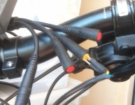
In my last order from BMSBattery, I got one of their 20A sinewave controllers that goes in the 09 bottle battery. It comes as a kit with included LCD, PAS, etc. The PAS doesn't function. I opened up the controller compartment to see four wires joined to the pcb from the PAS connector, so there must be two signal wires, which must mean a double hall arrangement, though from the outside, it looks like a standard cheapo 8 pole PAS. I believe that dual hall PAS sensors are handed, so I'm wondering if it should be fitted to the left side, or what would happen if I reversed the two signal wires on the pcb? Anybody got on comments on this?
You are using an out of date browser. It may not display this or other websites correctly.
You should upgrade or use an alternative browser.
You should upgrade or use an alternative browser.
4-wire PAS
- Thread starter d8veh
- Start date
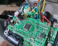
Today, I established that the four wires are red, black, green and yellow. The PAS is indeed the standard cheapo 3-wire one. The yellow is not connected. I established that with the green wire lifted, it pulses on and off to the red wire, but when connected to the PCB, it stays at 5v. I guess that there's a fault in the PCB. It's impossible to trace the fault because the PCBs are soldered in a stack - bummer! This is a photo of my previous one which is the same except the green and yellow are reversed. I think I might try swapping them over in my new one to see if it makes a difference.


I switched the PAS signal to the yellow wire. The signal is now pulsing, but still no motor turning. It's working on the throttle, so I'm now wondering if this controller only works with a four wire PAS. The last one they sent me had a different PAS.
thetimmy
100 mW
d8veh said:I switched the PAS signal to the yellow wire. The signal is now pulsing, but still no motor turning. It's working on the throttle, so I'm now wondering if this controller only works with a four wire PAS. The last one they sent me had a different PAS.
I was going to order the same controller with the 48V bottle battery. https://bmsbattery.com/ebike-battery/681-48v10ah-bottle-09-e-bike-battery-pack-battery.html
Have you made any progress?
BMSBattery.com states "It only fits the motor with inner speed sensor. Please make sure your motor has inner speed sensor. It doesn't fit the external speed sensor." I purchased a used motor from a kit like this http://www.ebay.com/itm/26-Electric...-Kit-eBike-Rear-Wheel-48V-1000W-/370934929537, if this motor lacks an internal speed sensor, what will the results be?
I failed on the PAS. There's a fault somewhere, but I don't know where. I'd need to get another set to see where the difference is. I converted a bike using the battery with the included 20 amp controller and everything worked OK apart from the speed display. For the one I have now, I bought just the controller because I already had the battery. The PAS is different. Unfortunately, I don't have the previous bike anymore to compare it.
The speed display is easily fixed. You need an external wheel-speed sensor. You drill a hole in the case to run the wire through and solder the three speed sensor wires to the pcb. Be careful to remove all the swarf from drilling. Don't let it get near the pcb. For the signal wire, you have to cut the white motor wire and join it to the new speed sensor one. In the photo, the red wire is soldered at the top left and the black is soldered at the bottom left to a spare pad next to another black, but be careful because there's a spare pad right next to it that isn't ground. It would be easy to bridge the two. If you want you can splice the red and black wires to the other red and lack wires in the compartment without going near the pcb. Actually, this is the first one I did, where I spliced the black wires. Note that there's two whites. The speed signal is the the one soldered in the lower position with the yellow heatshrink on it. The speed sensor bundle is the thichk black one at the top left with a zip-tie around it to take any external tension off it.

The speed display is easily fixed. You need an external wheel-speed sensor. You drill a hole in the case to run the wire through and solder the three speed sensor wires to the pcb. Be careful to remove all the swarf from drilling. Don't let it get near the pcb. For the signal wire, you have to cut the white motor wire and join it to the new speed sensor one. In the photo, the red wire is soldered at the top left and the black is soldered at the bottom left to a spare pad next to another black, but be careful because there's a spare pad right next to it that isn't ground. It would be easy to bridge the two. If you want you can splice the red and black wires to the other red and lack wires in the compartment without going near the pcb. Actually, this is the first one I did, where I spliced the black wires. Note that there's two whites. The speed signal is the the one soldered in the lower position with the yellow heatshrink on it. The speed sensor bundle is the thichk black one at the top left with a zip-tie around it to take any external tension off it.

thetimmy
100 mW
The motor I intend to connect to this kit is similar to this, https://bmsbattery.com/ebike-kit/469-q11-48v1kw-front-driving-disc-brake-hub-motor-ebike-kit.html.html. [/url]
This uses 8 wires, 3 phase wires power the motor, 3 hall sensor wires control the speed, and a +5v & ground for powering the hall sensor.
The controller https://bmsbattery.com/controller/698-sine-wave-controller-for-09-case-controller.html uses 9 wires, identical in function to above, but with an additional white wire for a speed sensor.
Can I connect the 5V and ground wires of the speed sensor https://bmsbattery.com/ebike-kit/661-king-meter-speed-sensor-ebike-kit.html to the 5v & Ground of the hall sensor? I would purchase an additional waterproof cable https://bmsbattery.com/ebike-parts/...e-female-connector-cable-for-motor-parts.html and avoid drilling holes into the controller.
Based on your description it appears that you tied into the same 5V that the hall sensor power uses, so the 5V output provided to the hall sensor should provide enough current to power both the hall sensor and speed sensor
Thank you for your help.
Ya - even cheapo PAS sensors can have two halls internally to determine pedal direction. Generally a tiny bit of electronics in the sensor housing with the halls just suppresses the single output signal when pedaled in reverse. Here it looks like they just took the simple route and ran the two hall signals to the main board to save on the bit of electronics in the sensor housing since they were building the controller themselves anyway - easier to do in firmware.d8veh said:I opened up the controller compartment to see four wires joined to the pcb from the PAS connector, so there must be two signal wires, which must mean a double hall arrangement, though from the outside, it looks like a standard cheapo 8 pole PAS. I believe that dual hall PAS sensors are handed, so I'm wondering if it should be fitted to the left side, or what would happen if I reversed the two signal wires on the pcb?
The two halls are offset an provide a quadrature encoding like so:
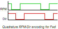
Examining the state of the Dir signal on the rising edge of the RPM signal tells the direction (look at the waveforms going left-to-right or right-to-left). Switching the wires inverts the sense of the Dir signal and so switches the 'handedness' of the PAS-wheel mount.
Hello d8veh,
I have the same problem : the PAS is not working...
My second problem is that the throttle had not the new yellow plug, so I am stuck !!!
I did a little searches concerning the wires :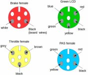
I have informations concerning the green plug (LCD) and blue (PAS) but have not yet done the drawing if you want !
Could you tell me which throttle wire to connect to the yellow female plug ?
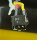
It seems that red is 5V black Ground and yellow signal (logical), as mentionned here :
http://dscl.lcsr.jhu.edu/main/images/3/31/SS49e_Hall_Sensor_Datasheet.pdf
I have the same problem : the PAS is not working...
My second problem is that the throttle had not the new yellow plug, so I am stuck !!!
I did a little searches concerning the wires :

I have informations concerning the green plug (LCD) and blue (PAS) but have not yet done the drawing if you want !
Could you tell me which throttle wire to connect to the yellow female plug ?

It seems that red is 5V black Ground and yellow signal (logical), as mentionned here :
http://dscl.lcsr.jhu.edu/main/images/3/31/SS49e_Hall_Sensor_Datasheet.pdf
My board (for the colors mentioned on the above drawings) :
Comment : the green S1 is in fact a white wire see at the top of the picture ! (the speed sensor i think)
The other white is near the yellow (the one to the command LCD brake throttle i think, yes should be the brake i noted last time on a draft)
In fact seems to be the contrary with your picture ? yours wiring seems strange !!! my hall motor are abc hg hv but on yours there are empty holes !!!! ==> I guess red end black are welded somewhere else !
I wrote to chn_1@163.com (http://www.szktdz.com) to obtain board informations ... they told me to ask the seller (bms) ... RRRRRRRRRRRR :x
I was very disappointed when I first opened the case concerning the quality of the welding and the mess with wires ...
It works !!! Thanks for the help !
So the problem is the PAS too...
Asked bms to send me the good throttle with plug and told them the PAS had a big problem ... wait and see !
Do you know what's the brand of these colored plugs and where to find them ?
So the problem is the PAS too...
Asked bms to send me the good throttle with plug and told them the PAS had a big problem ... wait and see !
Do you know what's the brand of these colored plugs and where to find them ?
thetimmy
100 mW
Any update on this? I plan on buying the same kit to power an old (but working excellently) 48V 1000W Direct Drive front wheel drive motor that lacks an internal speed sensor.
BMS Battery indicates that an internal speed sensor is required, but I think an external sensor & some soldering can make it all work
BMS Battery indicates that an internal speed sensor is required, but I think an external sensor & some soldering can make it all work
Same PAS problem here. All works (48V SO9 20amp controller) on the throttle but no pas sensor mode.
Wrote 3x to Jack a BMS but no reply.
In the mean time tried every combination of magnet disc and sensor directions but nothing.
By the way. I noticed the large resistor besides the board gets very hot when the board is powered.
I´m afraid it migth fail sooner or later.
Same on your controllers?
Wrote 3x to Jack a BMS but no reply.
In the mean time tried every combination of magnet disc and sensor directions but nothing.
By the way. I noticed the large resistor besides the board gets very hot when the board is powered.
I´m afraid it migth fail sooner or later.
Same on your controllers?
puregsr
100 W
Just got the same kit with a Q100H motor. Hooked everything up and bench tested it. Initially PAS refused to work, but playing with the P and C settings, it seemed to work now. I'll report back after I have it installed.
puregsr
100 W
I finally got it all hooked up and running.
Here are my settings:
p settings: 145, 0, 0, 0, 08
c settings: 03, 0, 1, 0, 10, 3, 1, 0, 0, n, 0, 4, 1, 2
I think the most important ones are probably the P2 and P3 settings to get the PAS working. I played around with P1 setting to get the speed right, but then trip meter is all wrong because it's only counting when power is supplied.
Similar threads
- Replies
- 5
- Views
- 1,218
- Replies
- 7
- Views
- 548


