wrong direction

miro13car

100 kW
Joined
Mar 26, 2007
Messages
1,905
Location
Calgary, Canada
Hi
Does anybody know what would be a reason for brushless motor to turn in opposite direction. Speed is controlled by Hall sensor, is polarity important on hall sensor?
Voltage to the motor is NOT reversed.
MC
 
If it's a crystalyte controller, there's a key switch on the side for reverse on trikes.
 
Flip two phases around any 2, hall sensors are polarity dependant dont swap the power to them, also as xyster says try flipping the reversal switch.

Depending on who you got your controller from some vendors disconnect the reversal switch inside to stop people reversing the motors, just undo the four screws on the end plate and check its connected to the switch.

Cheers

Knoxie
 
Short of what's been mentioned above, you could be misreading what direction it's supposed to be turning.

Also, if it's a front hub motor you can flip the wheel around and be done with it.
 
Mathurin said:
Short of what's been mentioned above, you could be misreading what direction it's supposed to be turning. Also, if it's a front hub motor, you can flip the wheel around and be done with it.

That reminds me: on the old forum I remember somebody mentioned hubmotors sold with the turning-direction arrow sticker pointing the wrong direction.
 
xyster said:
That reminds me: on the old forum I remember somebody mentioned hubmotors sold with the turning-direction arrow sticker pointing the wrong direction.

Yep, I seem to recall that with a Crystalyte. My Toprun had the sticker on backwards too.
 
I had that happen on my 407 front motor.

The motor has Hall wires and the 3 phase wires.. and works as directed by the arrow with an Instant Start controller...

However.

When i conected a Pedal-First controller to this same motor.. it ran in reverse.. I swapped out the Yellow and Blue phase wires.. kept the Green with Green and it works just fine.. with the same amperage at no-load..

Your situation could be different.. but that was my experience with one of them so far. .. The red arrow is potentially to point the way to the coffee machine in the shop, or so i'm told :p
 
That reminds me: on the old forum I remember somebody mentioned hubmotors sold with the turning-direction arrow sticker pointing the wrong direction.
My first hub did that - the arrow was reverse to the direction of rotation. Totally confused me.
 
Thank for answers, all of you.

Problem still not solved.
You all need more details.
It is TF rear motor, it is 7 phase motor , I took off wheels for truing, but on my last ride before it I notice that motor was pulsing/not working fluently/ as usual.
Next I fixed my battery board inside front wheel where comm port was shorten by white deposit.
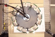
Before final bike assembly I opened rear motor with controller in it just to check for water/condensation damage, pulled two 2 tiny pin connectors inside and applied dialectric grease to them. Wires from these connectors goes into windings of electromagnets. I guess they are not connected to heavy bare windings wires. Are they temp sensors i GUESS, cannot be hall sensors inside pole winding wires?
Why only 2?
I thought about faulty hall sensor throttle.
I have a feeling problem might be outside of wheel with faulty hall throttle.
Could such throttle cause this?
In general motor wheel on TF fits only one way.
Thank you again for answering
MC
 
any chance one of the connectors got reversed? They're usually keyed to prevent this. A thermistor shouldn't have anything to do with direction. Swapping the hall sensor positions would be the most likely cause.

It's also possible the controller has a reverse function that got accidently activated by a tiny piece of conductive crap on the board.
 
Hey Miro, great news about getting you battery hub working.
Bummer about the motor. :(
Case of one step forward, two steps backward eh?
FYI, The guys at the TFF are working on stuffin Lipoly into the front hub & could use your help.

Some people that have had posted a similar problem have resolved them by cleaning dust off the BCD timing code on the inside cover and the optical commutation sensors. If that's not the case or have already tried that, then perhaps a sensor got bumped out of position or perhaps the cover requires alignment. Though I think it would be keyed in some manner to prevent that, but best double check. Don't have more to offer than that, so good luck!
 

Attachments

  • WCLalpha xploded view.jpg
    WCLalpha xploded view.jpg
    67.6 KB · Views: 3,213
  • WCLalpha stator.jpg
    WCLalpha stator.jpg
    49.5 KB · Views: 3,212
Hi
Thank you Fetcher and

Toorbought, you opend my eyes.
Yes, inside of cover has big white-black strips and there is small V-shaped PCB with tiny sensors 5 or 6 of them. They are strange like tiny squares
in pairs, one sender one receiver?
Optical pick up? I always thought when I look at them that they are speed sensors!!!
Oh my God, mybe I there is one particular cover position it should be placed? Now how on Earth I am going remeber?
Silly me I didn't mark position!!
You gave me a lot to think about.
Dusting?
There is sparkingly clean inside cover, no spackle of dust.
No problem I can get pictures. Problem will be zooming on detailes.
My Sony works closest 10 cm for zooming, next is blurring.
MC
Thank you so much AND I am asking for more.
 
miro13car said:
They are strange like tiny squares
in pairs, one sender one receiver?
Optical pick up? I always thought when I look at them that they are speed sensors!!!
Oh my God, mybe I there is one particular cover position it should be placed? Now how on Earth I am going remeber?
Silly me I didn't mark position!!

Yes, they sound like optical sensors. Are the encoder stripes attached to the cover? If so, the position would make a difference and likely explain the problem). How many possible combinations are there? Marking the position before disassembly sounds like a good idea.

I've never seen the insides of a TF other than the picutres you posted, which lack the detail to see the sensors.
 
Thank`s Fetcher.
Am I missing something? But shouldn't really matter in what position cover is bolted in?
You see there is pattern of wedge shape white and black painted .
All back of cover is divided like a cake in 8 black and 8 white strips, just like you cut a cake : 8 black and 8 white all equal parts painted.
There are exactely 7 sensors very close to the edge stator.
So every time bicycle is left in random sensor-strip pattern. So why would it matter how cover is aligned???
....Unless....
There is some inisialization procedure for processor controlling FETs.
Meaning, once wheel turns right way processor remember.
Or I am missing something??
MC
 
The processor needs to know where the magnets are in order to fire the coils at the right time. From your description, you could unbolt the cover and rotate it one bolt hole in either direction, then rebolt it .

How many bolts are there?
 
Fetcher ,
There are 9 bolts.
Motor turns in right direction now.
Problem solved , because thanks to advice from this forum.
I repositioned the cover matching screwdriver nicks I left when I was prying it loose. After that I disconnected battery for a while to reset and depower completely including discharging caps if any.
I power back on and viola wheel turned rigt way.
Conclusion:
commutation sensors are optical on TF motors
There are 7 of them , they match number of phases, also 7.
Right pattern of reading black-white strips must be estabilished first time on processor initialization.
Learned:
Always mark position of cover before loosening screws to open it.
Thank you all for help.
I am typing this from work after riding 9km.
MC
 
Excellent!
We really don't know a lot about the TF motors, so it's nice when we figure something out.

Next we'll have to work on boosting the power :twisted:
 
Back
Top