Blew my controller. Please advise......

StudEbiker

100 kW
Joined
Apr 13, 2009
Messages
1,999
Location
Ashland, OR, USA
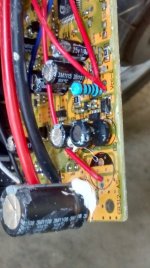
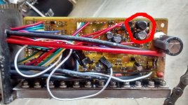
So my controller got damaged while getting near the top of the largest climb in my town. I finally got around to opening it up today and here are a couple of pictures for everyone to analyze.

controller.jpg
controller2.jpg

This is my first attempt to repair a controller, but it looks to me like I blew a 25V 1000uf capacitor that's circled in red. Can someone confirm my diagnosis. Is this something that Radio Shack might have, or am I going to have to get it through the mail?? I've got an old charger lying around to that I could scavenge for parts if there might be one in there.
 
What's wrong with the cap? Is it up or down in value from it's marking, when you test it out of circuit?

I don't see any visible damage (swelling, leaking) on any of the electrolytic caps in either pic.

What specifically does the controller do or not do now that it didn't or did do before?
 
i think the part next to DG is an inductor for the DC converter on the front end.

if we knew how it failed we might be able to help. you can test the mosfets with the diode tester on your DVM.
 
Thanks for the help guys.

I was right at the top of a very big climb here in town. I had ridden up slowly and tried to keep watts below 1000 to take it easy on the motor. I had done the climb earlier in the week successfully using the same technique. Literally as I was at the top and about to put my foot down to stop, I heard a soft pffft sound and I lost the power to the motor. The CA was still displaying, but absolutely no power. Controller was very warm when I touched it but not so hot I couldn't keep my hand on it. That's about all I can tell you as far as how it failed.

That capacitor definitely doesn't "look" right to me. The way it is completely black now and the hourglass shape looks really strange to me, but I haven't seen as many open controllers as you guys have for sure.

I haven't done any testing. I don't even really know how to do any testing. Can you give me a couple of tests to start with and I'll report back.
 
Look at the component label on the silkscreen. Should be labeled L something. Sure looks like a radial inductor to me too.
https://www.google.com/search?client=ubuntu&channel=fs&q=radial+inductor+image&ie=utf-8&oe=utf-8
Visually inspect the fets. Many times you can see where the case has bubbled or cracked when they've gone bad.
 
StudEbiker said:
Okay. Can you give me some advice on what to do to diagnose the issue. You mentioned testing the rest with the diode funtc ion on a dmm. The've never done that, but I guess I'll do some searching and foind a thread that shows how to do that unless someone can link to a good one they know.

there is no thread on it.

everybody mosfet has a body diode because of the way the semiconductor device is manufactured. you can measure the body diode between the source leg and the drain leg.

in an n channel mosfet like used in these controller, the drain leg in the middle is always connected to the higher voltage side and does not conduct unless turned on by the gate voltage rising to 5-10V.

your DVM has a diode tester which pushes current out of the red probe, ie: it is at the plus voltage, and the current returns in the black probe.

so to test to see if the body diode is intact then you can put the red probe on the drain and the black probe on the source leg, the right leg. it should be open circuit.

then reverse the probes and put the red probe on the source leg and the black probe on the drain and you will see the body diode conduct. the display will read the forward bias of the body diode at the 1A current the DVM pushes.

test all of them to see if any of them is shorted and that will give you a lot of info since the forward bias should be identical in all of the mosfets unless they are damaged by heat, so they will all read the same forward bias.
 
StudEbiker said:
I was right at the top of a very big climb here in town. I had ridden up slowly and tried to keep watts below 1000 to take it easy on the motor. I had done the climb earlier in the week successfully using the same technique. Literally as I was at the top and about to put my foot down to stop, I heard a soft pffft sound and I lost the power to the motor. The CA was still displaying, but absolutely no power. Controller was very warm when I touched it but not so hot I couldn't keep my hand on it. That's about all I can tell you as far as how it failed.

I can't help you with the repair, other than to say that I've never seen a repaired controller end up a durable controller afterward.

What I can help with is the simple fact that going as slow as possible up a steep hill is the most torturous thing you can do to your system, and it's even more torturous on a controller run near its limits.

The reason is because despite the low power to climb at low speed, the controller must send very high phase current to the motor to create that power. Power in is battery current X voltage like we see reported by the CA, however, the power produced by the motor is rpm X torque. With rpm so low the controller sends a low voltage signal to the controller, simplistically stated as rpm/Kv, so the torque required is quite high. Torque is created by phase current not battery current, and those high phase currents sent as short spike of high current at the PWM frequency are very hard on the controller, because they're happening in simplistic terms at the phase current limits of the controller. That's my biggest problem with the often copied and shared phase current to battery current ratio of 2.5-1 or higher. That kind of setting is only marginally appropriate for people living on flat terrain and don't do repetitive stop start accelerations like people who don't know better tend to do, those who get stuck in stop-n-go traffic are similarly at risk.

That doesn't mean you must artificially limit performance, and even with horrible current limit settings you can avoid much of the risk by charging at hills. For the mountainous terrain around where I live, I learned that with my bikes, that as long as I maintained near 50% of top speed while climbing any incline regardless of throttle position that my system stayed out of the danger zone. All my ebikes at the time topped out at about 60mph, and I got very anxious any time I got caught behind slow trucks up a significant grade. If I couldn't quickly pass then a number of times I pulled over and waiting for a break in traffic.

FWIW the limits I applied to my system aren't something to follow, and controller temp isn't always a hard guide either. The thing to understand is how dangerous partial throttle can be for your system, because failures can sneak on you unexpectedly. I blew a couple grand worth of cheap controllers to develop a reasonable understanding of things to avoid. That came into focus in late 2010, once the real electronics experts started teaching us what happens in terms of phase vs battery current. Since then I've only had 1 controller failure other than supposedly new and tested controllers that were bad out of the box, and the one failure resulted from being told that a controller had regen that turned out to be plug braking. That controller failure occurred the first time I grabbed a handfull of regen brake continuously from 60mph down to a sharp 90° turn.

The low speed issue is so big, that I've seen 2 controllers blow on flat ground at speeds below 5mph. The one that happened to me was on a road so bumpy that I felt that speed was appropriate. The bumps caused my wrist to repeatedly pulse the throttle, and while there wasn't any significant surging of the bike or change in speed, the pulsing spikes of phase current were noticed by the controller in a deathly way. The other time was my sub 100lb daughter riding very cautiously in the flat grassy park on her first ebike ride. She repeatedly pulsed the throttle to ride along very slowly for just a few minutes until the controller sizzled and popped.
 
Thanks John. I appreciate that detailed response.

I haven't been to focused on my e-bike tech lately because for almost the last 2,000 miles on my bike I've barely had to do any maintenance other than adjusting the rear brake. (Front Sturmey-Archer hub never needs adjusting :D )

It was after this event that I recalled that going slowly up a grade really isn't a good thing at all for the controller. My mind at the time was protecting the motor.

As I am getting ready to order a battery from CellMan, I'll probably pick up another controller too and use this one as a backup assuming I can get it repaired.

I attempted to test the fets today, but I found it incredibly difficult to get the leads on all but a few of the fets. I think I am going to have to make some kind of smaller probe to use in conjunction with some alligator clips and probe in between the fet and where it attaches to the PCB between the heatsink.
 
and it usually is the hiside mosfet too that burns. it happens when you slow way down and often it will happen when there is full throttle and the motor is stalled. the hiside capacitor that supplies the current for the hiside gate driver needs to have motor turning to provide the cycles to pump up the hiside cap.

so gate voltage can drop as the cap discharges and the wheel is not moving. then the transistor goes into transistion and rapidly overheats. my theory along with john's discussion. for the stalled motor.

but you will know within a few minutes when you test them.
 
Check the fet on the right side of the pic. Not sure but maybe the screw is loose due to a melted bushing. That's just a guess. I have seen that on other controllers but not mine yet.

Did you get the whole setup from Paul? Mac motor, if so what turn and what size wheel? Just nosey.

Dan
 
DAND214 said:
Check the fet on the right side of the pic. Not sure but maybe the screw is loose due to a melted bushing. That's just a guess. I have seen that on other controllers but not mine yet.

Did you get the whole setup from Paul? Mac motor, if so what turn and what size wheel? Just nosey.

Dan

I got it used, but I'm pretty certain the previous owner got the whole thing from Paul.

It is 8T in a 20" (406) wheel.
 
the mosfets above the phase wire is called the high side and the ones below the phase wire are called the low side.

it is easy to test them by putting the voltmeter probes into the solder where the legs are soldered into the pcb on the underside of the pcb. should only take 2 or 3 minutes.
 
So in the first picture I posted, it looks like there are only two fets above the phase wires. Those are the two fets on the right most side of the picture correct? Those were two of the ones I was able to successfully test and they both seemed to be fine. The traces on the opposite side are heavily built up, so I don't see any way to test them from the other side of the board. There is a small gap between the pcb and the fets in between the heatsink where I think I can get a small probe in to test them, but I ran out of time yesterday. I don't anticipate having much time today either, but I'll try and get some more pictures today and post them up.
 
it is out of the case so just test them from underneath where there is nothing in the way.

all you have to do is walk the test probes down each mosfet and measure the drain to source on each one and they should all be open circuit. if one is shorted it will show 0V on the meter. there is no way to know which is bad in advance unless you can see the plastic case of the mosfet is discolored from heat or blown off.
 
Okay, I finally pulled my head out of my butt and I think I have some useful info.

I opened my eyes and saw how I could check the fets from the opposite side of the pcb.

Here are the results. First, with the red probe in the middle:
  • 1 - 0v
    2 - 0v
    3 - .513v
    4 - .513v
    5 - 0v
    6 - 0v
    7 - .513v
    8 - .513v
    9 - 0v
    10 - 0v
    11 - .512v
    12 - .513v

Then with the black probe middle:
  • 1 - .385v
    2 - .385v
    3 - .366v
    4 - .366v
    5 - .385v
    6 - .385v
    7 - .366v
    8 - .366v
    9 - .385v
    10 - .385v
    11 - .366v
    12 - .366v

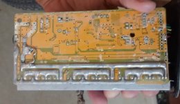
I've also attached a pic of the back side of the board.

IMG_20150813_175423516.jpg
 
the numbers do not make sense. they all appear shorted. o ohms on those 6 is more of a short than would be expected and the .512 Volts is unusual for a shorted mosfet imo. so without doing it myself it is hard to understand.

since the forward bias is the same and in the normal range then all would otherwise appear normal. but they should all be identical.

but as it appears, all of them are shorted.
 
Was your meter in diode check mode?

You might also try measuring across some of the capacitors, observing the polarity marked on the cap.
A good capacitor should start with a low reading and steadily increase for a time. If the reading does not change, the cap might be bad. Sometimes there are other parts in the circuit connected to them so the readings may look bad when they are really good.

The FET readings are strange. Looks like half of them are shorted.

I prefer making the FET measurements through the phase and power wires. Measure each phase wire (meter on diode check or ohms) against the positive battery wire, and again each one against the negative battery wire. Nothing should look shorted.
 
Back
Top