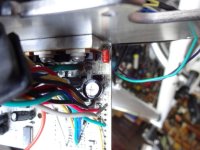
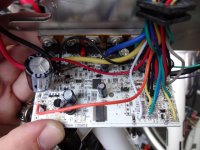
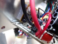
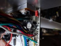
Well, it seems they keep failing and coming my way.. izip .. schwinn.. Raleigh.. Giant.. now iGo's !
This poor iGo came to me a couple months ago with battery issues, moisture got in there and caused the BMS to shut down, after checking all cell voltages and sun drying for a while it came back to life and all was good since.
Last week customer had a crash and the throttle wires got ripped out of the throttle body at the hall sensor itself.. but the bike kept running with pedal sensor input for another 5 days. then it quit ... and arrived here .
I replaced the throttle with a tested / known good unit, the display will power up, the head light will function on/off, the high medium low function changes with button presses but the motor will not budge.. Throttle and Pedal Sensor both not responding at all.
Pulled the wire harness out of the frame ( no fun... not a good wire harness .. ) and discovered color combo's mixed along the way but traced the throttle wires all the way to the controller and confirmed continuity, cut the throttle connector and soldered it to remove that possibility.
One of the brake levers was bent pretty bad so that was a possible issue.. tested the sensor and they are ok, i cut the wires from both just to make sure ( tested open circuit operating, closed circuit when brake lever pulled )
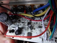
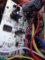
following the Red and Black wires from the throttle and pedal sensor to the controller board i get 1.2v on the throttle pins and 0.4v at the pedal sensor with the controller powered up and display lit.. .. i believe that should be 5v .. right ?


