upgrade a Stricker handbike (wheelchair tricycle) off road

Joined
May 5, 2016
Messages
12
Hi there,

I just want to tell everybody interested about upgrading an electically supported Stricker handbike (wheelchair tricycle) for way better off road capabilities, including changing the motor to solve thermal problems. This included also solving a good amount of mechanical problems. The idea is to share my experience and to help others.

Due to an accident, our son requires a wheel chair. He always liked and still likes riding through mud and pretty serious off road sections.

Impossible for a wheel chair? Yes :cry:

So we looked for a solution. First try was a non electric handbike, manufactured by the German Company Stricker, consisting of one wheel attaching to a wheel chair.

We made quite a few modifications for better off road capability:
- removing front tires from wheel chair for better ground clearance
- off road tire to the hand bike
- longer wheel base (rear axle behind end of the seat) for better stability and for more weight onto the front tire
- widening the track width by adding adapters of about 15cm to each side, now having slightly more than 1m in total for more side stability
- adding a stainless steel tow rope and connection rings (became helpful several times yet)
- replacing the mechanical disc brake with a hydraulic Shimano SLX with the cool tech laminated aluminium / steel disc

However, this did not really work. A teenager getting maybe 40 Watts out of his arms in a hilly area with pretty steep inclines on very muddy ground does not provide much fun. So we upgraded the handbike by the standard solution offered by Stricker. This consists of 36V LiIon batteries, 15A controller, pedal assist and a 6km/h limited hand switch. The motor is (was) a Bafang 8fun 250W geared motor. There was an Arduino installed to control the controller, doing more or less what the Cycle Analyst does.

We had pretty much fun on this, e.g. in northern Italy on the Ponale Road https://de.wikipedia.org/wiki/Ponalestraße.

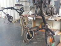
Attached are some pictures we took:
View attachment 7
IMG_0419.JPG
View attachment 5
IMG_6119.JPG
IMG_7061.JPG

However, we got more and more problems, due to motor overload.

We killed the motor at least twice. Replacement we got (was a used one, we got if for free after warranty so no complaints) already hat dark burnt windings and loose hall sensors... Pretty sure it already was pre damaged, smelled electric. Used Epoxy to reattach the halls. When getting aware of the problem, we even installed a ATF cooling. After a short while, this engine again was killed. Smoked on the bench when only spinning slowly.
IMG_0185.JPG
IMG_0190.JPG
IMG_1228.JPG

So we needed to really solve the issue. How I will explain in the next post.
 
So, what to do to solve our thermal problems?

Lessions learned: We needed a stronger motor. Not primarily because of more power or torque, but to take more thermal power before burning isolation off the wires. And we needed a temperatur surveillance to make sure not to destroy the next motor.

We finally ordered at http://www.ebike-solutions.com/ (German supplier) - the shop stuff was very helpful on technical questions in advance, they delivered quickly and the products appeared to be really good.

The new motor is again a geared motor, 500W, manufacturer is said to be Puma (did not find much about the motor on the web).
http://www.ebike-solutions.com/en/shop/motors/motors-over-250w/puma-rear-wheel-motor-500w~1.html

We took the one with 250rpm which turned out to be fine for the legal 25km/h speed limit and for the 20" wheel size.

Originally, we had a 8 gears cassette screwed onto the hub. Even though the web site recommended a washer between cassette and hub, this was not needed.

We as well ordered a torque arm:
http://www.ebike-solutions.com/en/s...-drive-motors-suspension-and-rigid-forks.html

And a new cable set due to changed wiring standards.

Even though the web shop warns from commutation problems and this motor has 16 pole pairs and internal gear reduction by factor five, the original Stricker controller works perfectly well. So no exchange required for this.

To check the temperature, we bought on ebay a silicone sealed mini LED thermometer working on an external 10k NTC. http://www.ebay.de/itm/151167218378

This was the shopping list.
 
Electrical problems to solve:

There were not too many :)

Electrically, the halls worked well. Commutation was not a problem as well.

We had to change the wires colors between motor and the controller and between halls and controller - initially when connecting colors 1:1 the motor did not spin. But, with the help of http://www.ebikes.ca/ help page, this was a quick fix. Hall cables need to be soldered due to different plugs used on both sided. Motor cables use both Anderson plugs, that can be easily changed in order. Like this, it worked:
IMG_1242.JPG

When connecting the thermometer to the motors sensor (soldering cable onto the plug pins) and providing 9V from a battery, it immediately showed the temperature. However, the 36 Volts out of the motor batteries seem to be a bit too much. First idea was to take voltage down by installing a resistor i line. Did not work. Then I upgraded this by soldering a LM317 voltage reduction board - did still not work at all. When unintendedly measuring the current on the power supply cable to the thermometer while ground was already unplugged I noticed, that there is some kind of connection between the measuring wires and ground in the motor, preventing from supplying the thermometer directly from the motor battery.

Quick fix: taping the 9V battery to the case:
IMG_1247.JPG

Mid term fix (parts are already ordered):
DC-DC converter from 40V (max. 45V) to 24V to reduce the voltage and additionally an insulating DC-DC converter 24V to 24V to provide power independent from the ground connection already available through the sensor.
Parts used:
http://www.ebay.de/itm/111979168690
http://www.ebay.de/itm/261969778358

To make it easier, I did not remove the old motor cable. So the new one needed to be squeezed through the sealing to go into the electric case, which needed some friendly force and some time:
IMG_1243.JPG

Finally just the cables needed to be stuffed into the case...
View attachment 2
 
Talking about the mechanical stuff:

When comparing both motors, the newer one is significantly bigger and heavier, which was both expected:
IMG_1229.JPG

OK, starting the replacement.

First surprise, the axle diameter is significantly bigger - this luckily turned out not to be a problem, since both axles have 10mm across the flattened sides.

Then we noticed, that the diameter of the nut flange is too big, colliding with the steel tube of the forge. Solution on the gears side was to grind the diameter of the flange down. On the opposing side, I did not want to take the sealed and heat shrinked cables apart which would have been necessary to take the nut out to grind it down as well. I found it to be possible to insert the axle with the nut when the nut is already screwed in to loosly scratch along the forks side - then it just matches into the space before the forks tube widens.
IMG_1231.JPG
View attachment 4

Next step was to find out, that the disc caliper collides with the motor. There is already an aluminium spacer provided with the motor - but two would have been better to slightly widen the distance between motor and disc and caliper as well. To solve this, we installed two M5 washers below each screw tightening the brake disc. We used slightly longer screws as well (not too long to block the motor!). Washers seem to be not ideal because longer leverage, but so far this seems to work very well.
View attachment 7
IMG_1235.JPG

How to mount the torque arm? It turned out to work only on one side and only if being bent slightly to make space for the chain. Grinding down one side a bit later on helps mounting the axle with the torque arm. We had to open one of the openings of the second part using a drill to be able to attach it to an existing hole of the fork. A washer was required to give room for the chain. Always use self securing nuts.
IMG_1234.JPG
IMG_1238.JPG
IMG_1239.JPG
IMG_1240.JPG

On the non gears side we noticed to now have space between motor and caliper, but when tightening the axle nuts not enough space between frame and caliper to properly mount the caliper. So another washer was mandatory. Now the axles width is about 3mm wider than the opening of the fork. I feel this not being of any problem, aside the fact that mounting the wheel is a bit cumbersome.

We also found out, that even though the wheel is pretty much centered the first two gears do not work any more. This also goes partly to the fact, that the new rim is significantly wider than the old one, making also the tire width wider. And even before doing the modification, the chain was almost touching the tire. So I mechanically limited the derailleur to start with third gear. This is not a big problem, since we have another gear reduction on board (Schlumpf mountain drive).
IMG_1241.JPG
 
And the result?

Great!!! :D

Much more power and torque. Even significantly bigger range (seems like the motor has a way better efficiency).

Now we know about the temperature. Light use is between 30 and 40°C. Very steep and long inclines (almost slipping front wheel on asphalt) or inclining and very wet, muddy forest paths can get the temperature up to about 85°C. Once we reached this point, we made a rest to let the motor (and myself on a non powered mountain bike) cool down a bit.

Our son has so much fun with the improvements and both of us are very happy to have done this.

However, we have alread plans for the next project, a real serious off road hand bike:
http://www.sport-on.com/#!fat-explorer-1/oocod
ScreenShot406.jpg

This uses a motor from Sunstar (http://www.sunstaribike.com/e-bike-mid-motor-s03/s03-drive-unit/). Like all standard ebike controls, this is adapted to work for people pedaling by their feet. So the plan is to use the cycle analyst and get it running with the Sunstar S03+ to be able to adapt this to our needs. This project will take some time, will tell about this in another forum entry.
 
Nice work making the adaptations.

Wider tires and a larger motor will surely work better.
 
Aloha, WOW what a ride. There are not very many trails like that in Hawaii, mostly roads in various states of repair. So for ON-Road I use one 8 speed clip on with coaster brake. The electric one is a 1000w 14" wheel model electric Leaf motor that runs very fast 55kph @ 66volt 5ah Lipo Battery. I get about 8 miles traveling duration. Picture of my "Docking Station" and an earlier picture model of my 350w motor unit and a 1/3 finished electric trike.

francis


View attachment 3
mybuild.jpg
moped512kjpg.jpg
 

Attachments

  • 20160507_170657.jpg
    20160507_170657.jpg
    40.1 KB · Views: 1,494
That's quite impressive - do you do all that mechanical stuff yourselve? Hawaii must be a cool place to climb initially and then having fun back down again :wink:
 
We made intensive tests and long drives yet and we are super happy with the result. More torque and even longer battery life. A few pictures will show the results:

IMG_1248.JPG

vlcsnap-2016-05-17-16h45m57s009.jpg

IMG_1256.JPG

IMG_1254.JPG
 
Yesterday we finished the electrical work: Adding the non insulating 40V to 24V converter and the isolating 24V to 15V converter to supply the temperature gauge. Works pretty well :)
 
Aloha,the more I see your trike, I am thinking the tires are either too skinny for mud and too fat for roadway. Would you not be better off lacing the hub to a motorcycle rim and mounting a car tire? You do not even need the rounded edges of the bike/motorcycle tire, but could use the flat contact of the car tyre to give you all the ground grip and boyancy that you can get.

francis
 
Back
Top