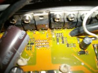
Waterlogged bike

nutnspecial

10 MW
Joined
Mar 3, 2015
Messages
3,753
Location
PA
I decided to cross a low spot on the river for the first time this year. I guess it wasn't low enough yet. . . :mrgreen:

The water was just high enough to cover bottom of controller (em3 18x 4110) and motor (sensored bht mid) and I also went in with a little gusto causing splashing that prob didn't help. It was a short slowish trip in the water and everything barely got more wet than crossing before. My harness exits the top of controller and didn't get wet at all.

The CA monitors as usual, and the headlight works. Both of which are pack voltage thru controller.
The hwbs (ebrake) lights when engaged as usual (low voltage side). This sensor was the first thing I thought of since it's lowest on the bike.

The throttle does nothing.
Bike dead in the water so to speak.

I don't see how the symptom fits motor + water, even if submersed.
Hwbs operates normally (gauging from led).
Ca (monitor only) and headlight as normal.

What do you think I should look at? Controller? Is there a normal failure mode that fits my symptom?
 
Shit well I unhooked ebrake and same thing.
Checked harness connections.

Pulled controller guts and motor cover. Both appear fine and dry enough with nothing visibly or smelling fried. However the bottom cover of controller had worked a few screws out and was not tight at all. There's a little corrosion here and there, but seemed and smelled ok. I'll clean up the pcb tomorrow with a nylon brush and go get my multimeter to start testing crap.

I kinda expected water damage to cause very obvious component (caps, halls) failure though.
 
nutspecial said:
The throttle does nothing.
Bike dead in the water so to speak.
Hey now, water and electronics are a no no. You should know better... :mrgreen:
Sorry dood. That really sucks.

I'd start by checking the throttle. Get you a digital meter and check it for resistance changes when you move the throttle up and down.
Next, I would pop off the cover on the controller and see if any water got inside. This should have been your very 1st move when it stopped working. Electronics can survive water, just not when power is running through them.
Maybe could be an e-brake gone bad, not allowing power to the motor? Can't remember if you had e-brakes or not.
I also wonder if your controller was hot when the water hit it. Thinking it could have fried some FETs with an extreme temp change.

Start with those first 2 things, then move on to other areas. Got to use the systematic approach of troubleshooting by elimination. Hopefully its just the throttle or an e-brake.


EDIT: Nevermind the e-brake comment. You replied while I was typing mine. LoL
 
And also, as indicated by throttle and harness staying dry, and the low voltage side of controller appearing functional, and the confirmation above of 4.x volts to throttle-

I just pulled the heatshrink and confirmed normal throttle operation from .78 - 3.56v wot
Ebrake should be ruled out too, with visual confirmation of lit led only when activated, and also by disconnecting the two signal wires for test.

So I think it sounds like the motor with those cont tests. But I don't understand how all three phases would be shorted together like that. Water shouldn't even do that right? And controller and motor were very cool, I was just nosing around in the woods beforehand for about 10 min. A little baffled here.
 
I am not familiar with that motor. If I was able to see it up close in person I might have more of an idea as to if/how water got in.
Are not these motors sealed up tight? Do not see how water would get into it unless through the hole where the wires go in or around the output shaft. Shaft area should be sealed up tight too.
Do the wires on that motor come out on the top or the bottom of the casing? Remember, water can get in tight spaces with capillary action. Heat from the motor could pull cool water inwards.

If that motor has bolts holding on either endcaps, pull them out and pop off the back of the motor. Easy on the wires though.
Most of the time the holes the casing bolts go into are separate from the inner casing. If those bolts actually go into the inside of the case, that possibly could be another point of entry.
 
RageNR said:
I'd start by checking the throttle. Get you a digital meter and check it for resistance changes when you move the throttle up and down.
Hall throttles can't be measured for resistance like potentiometer throttles can; most ebike kits use hall throttles.

I also wonder if your controller was hot when the water hit it. Thinking it could have fried some FETs with an extreme temp change.
That's extremely unlikely--they'd have to be so hot the solder was melting before you could damage them like that. :) At that point, they'd've died from the heat anyway.

nutspecial said:
4.6v to halls
Do you mean at hall signal wire, ground wire, or power wire?
And is that with motor connected or disconnected?

20k cont (zeros @.01) = ~3.9 between the 3 halls
If you mean a resistance measurement, that's not really useful as they are not really resistive-function devices. You need to measure their voltages when powered on, connected to the controller, and hand-rotate the motor.

There are a lot of troubleshooting threads that discuss how to test controllers and motors for fuctionality. I'd recommend going thru those, or at least the documents on the wiki and / or the Grin Tech site, to get all the steps. :)


phases: I have full continuity (20k, .01v) between all three phases on motor side - I am pretty sure that's bad?
All phases are tied together inside the motor, and the windings are just wire, so even at the lowest possible setting on a typical multimeter, you'll read essentially a dead short between them, whether good or bad.

Now, if you read a short between a phase and the stator or axle, that's another story. ;)
 
RageNR said:
Are not these motors sealed up tight? Do not see how water would get into it unless through the hole where the wires go in or around the output shaft. Shaft area should be sealed up tight too.
Anything that moves isn't completely sealed, by nature, so bearings, shafts, etc are all potential sources of ingress. See Justin's tests from a while back (linked on the Grin Tech blog page, and also here on ES in a thread about it somewhere). It might not be much...but it can get in. And once in, it cant' get out as easily, so it starts to corrode things.


Remember, water can get in tight spaces with capillary action. Heat from the motor could pull cool water inwards. ..
[/quote]
It's not really the heat that pulls cool water in. It's that heat pushes air out (because it expands), then as the mtoor cools when wet down with rain/etc, it sucks water in. See Justin's tests....
 
amberwolf said:
It's not really the heat that pulls cool water in. It's that heat pushes air out (because it expands), then as the mtoor cools when wet down with rain/etc, it sucks water in. See Justin's tests....
Hmm, that's an interesting theory. I know from my 10+yrs of commercial A/C experience, heat will indeed attract water in tight places. I've seen it crawl up wires and through barriers that were in place to prevent water penetration. Most were not air tight. I supposed for a laterally mounted sealed motor, the conditions could be different.
There are particular condenser fan motors that have drain plugs on them (mounted shaft up). If you do not remove the plug on the bottom facing side, the motor will fail from moisture intrusion. Usually takes about 1yr.
Maybe that type of water intrusion is based on expanding hot air, thus pulling in moisture from the surrounding cooler air? I'll have to look into that.
amberwolf said:
Hall throttles can't be measured for resistance like potentiometer throttles can; most ebike kits use hall throttles.
Was not aware of that. Thanks for the insight. Wonder what the el' cheapo twisty that came with my Cyclone kit is? What I do know is it is extremely touchy and not smooth at all. Hard to get anything steady between minimum and maximum throttle.
amberwolf said:
That's extremely unlikely--they'd have to be so hot the solder was melting before you could damage them like that. :) At that point, they'd've died from the heat anyway.
I've seen circuit board traces fracture when hit with water. Mind you, these were sealed boards. Board wouldn't blow, but the trace would break or be intermittent.
I have doubts that the FETs could be that vulnerable. Was just thinking outside the box. Who knows the durability of these cheap Chinese components.
 
Thanks guys. AW that's some really helpful stuff, I imagined the phases wound separate. I'll check my other bht as control as needed, swap in another throttle, do a hall test and test phases to grounds, and probably also order another controller (for next build . . or catastrophe) as well.

Also- it was 4x volts to throttle. Confirmed good ground and .xx tp 3.xx on signal wire on operation. That was full circuit.
Confirmed good power and ground for halls. I tested controller side, but not when connected to motor.
I'll reread the stuff on controller and hall testing for accurate testing of voltage switching with rotation.


Good news is a got a ridiculous but highly efficient bike from the neighbors scrap pile to ride around town in. Actually also got what looks like an 80's huffy. Both garaged.

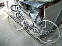
This one is called 'panasonic' but looks just like this road bike with double butted top tube, 12 spd. I will ride for a while, but will thank it for it's service by doing something extreme for it :D

 
Hmm, doesn't look like much water got anywhere. I am leaning towards the controller.

Those Panasonic bikes are actually pretty popular old street bikes. Some can be worth a few bucks. Not sure on that particular model. Lots of collectors that like the older bikes.

If you had a better meter, you could check the caps to see if they are good. You have to remove at least one leg off the board to test it.
 
Thanks for the tips, it's not beyond me to get a fluke or whatever and get into the pcb, but it helps knowing what you're looking for/ doing lol.

It's a sport 1000. Holds air. Just went across town at decent speed. Not only lighter than mantra to start, but without the 30+ lbs of E and wide tires it's a treat to pedal fast. It's been 20years since I rode a roadbike, so it's nice the klein is soggy and my route/vehicle changed today to hit the window before the panasonic and the old huffy went for scrap- can't believe people thro this stuff out, and it's really all I need to cross town at a decent pace.

The trails are likely another story (or going much faster than 20mph on flat) but I'll have to try heheheh lol


:D so I'll keep this updated on questions and/or a final fix to my klein 'man_atee'
wawa.jpg
 
nutspecial said:
Thanks for the tips, it's not beyond me to get a fluke or whatever and get into the pcb, but it helps knowing what you're looking for/ doing lol.
It's really easy. You do have to remove one leg of the cap to check with the meter. You can just test with a good meter to tell if it has failed or not. Here is a video explaining how to do that (for your case, a meter is fine): https://www.youtube.com/watch?v=o6kPLx2AmFo
Notice the meter setting on the Fluke. That yellow symbol is for capacitance. The white triangle symbol next to it is for checking diodes.
Make sure to connector your meter leads to the cap correctly. Cap has a large stripe down the side indicating negative.
nutspecial said:
It's a sport 1000. Holds air. Just went across town at decent speed. Not only lighter than mantra to start, but without the 30+ lbs of E and wide tires it's a treat to pedal fast. It's been 20years since I rode a roadbike, so it's nice the klein is soggy and my route/vehicle changed today to hit the window before the panasonic and the old huffy went for scrap- can't believe people thro this stuff out
That's a good find for free. Find some numbers on it so you can figure out the year model. Then look up the value on the bluebook. (looks to be a 1984 women's, worth 100-150 possibly)
I have to agree with you on the Klein. The ride is pretty plush. Perfect for my setup. Funny enough, even after adding the Cyclone kit it does not feel all that different. A little heavier, but still quick to ride. Has had little impact on my speed except for quick cornering.
I will be updating my build thread here in a bit. Trying to collect some pictures to make a post.
nutspecial said:
The trails are likely another story (or going much faster than 20mph on flat) but I'll have to try heheheh lol]
I've had the Klein up to 22.4mph on a smooth paved HWY feeder. Does that count? Can't sustain that, but can 19mph. And I am in like piss poor shape. That was day 3 of riding after I bought her.
Actually got it up to just below 27mph on a quick sprint, then slammed on the brakes. Wanted to test out the "stink-bug" effect. Not as noticeable as I was told.
I nearly got creamed in the Academy Sports parking lot two nights ago at 2am. Lady came bolting across the front of the store as I came around the side from the back.
The rim crushers work VERY well. Stood the bike on the front wheel about 10ft from her passenger door (nearly flipped). Think I was doing like 17mph. Quick reaction, quick save.
Took a while for that nut to come back down...
 
Wow I thought similarly about the year (84). I think the huffy is more 'stylish' from the same era, and guess both are at least steel. The roadbike is cromoly, and nice, and that's amazing people would pay that. Prob because they usually just get thrown away- supply/demand. Will def check that out though, for the huffy too.

Well that was pretty quick for your kit and battery choice and install! I can't wait to hear (and see) more on the bike and kit. Yes I agree the vbrakes are excellent on them, they do XC excellent, and wheelstands can be fun (and useful)!

I have no idea how many 'watts' difference there is between pedalling up speed on a light 80psi narrow-tire roadbike, but it's definitely alot less than a full susp 70lb bike with thick tubes tires and rims @ 35psi. To be fair, the comparison might be close in difference between that same 70lb bike and a 90lb DD hub build. Maybe 75 human watts.

___________________
Thanks for the info. I guess because you suggest it, that it's common knowledge a controller might act this way with a blown cap? There does look like a little electrolyte had leaked on the bottom one, or it's just some oxidation, but nothing spectacular (bulge/burn). Also water shouldn't have really caused that type of cap failure from what I understand.

I'll add desolder/test suspicious cap to the list of things to check and test.
 
nutspecial said:
I have no idea how many 'watts' difference there is between pedalling up speed on a light 80psi narrow-tire roadbike, but it's definitely alot less than a full susp 70lb bike with thick tubes tires and rims @ 35psi. To be fair, the comparison might be close in difference between that same 70lb bike and a 90lb DD hub build. Maybe 75 human watts.
Absolutely, no doubt. Last road bike I ever rode was back when I was a kid. Thereabout 20ish years ago. I've wondered recently how fast I could go on one, just as a comparison to the Klein. I was actually very impressed with how agile the Klein was after riding it for the 1st time. The added kit weight mostly affects my handling vs the pedal force needed. There is a diff, but not much IMHO. I rode over 100miles the week before I put the kit on, so I would have a good feeling for the difference afterwards.

nutspecial said:
Thanks for the info. I guess because you suggest it, that it's common knowledge a controller might act this way with a blown cap? There does look like a little electrolyte had leaked on the bottom one, or it's just some oxidation, but nothing spectacular (bulge/burn). Also water shouldn't have really caused that type of cap failure from what I understand.
I am no e-bike expert, or even electronics for that matter. But I do have quite a bit of experience with various equipment and circuit boards.
The electrolytic capacitors have an exposed top. Where it would vent in the case of extreme internal pressures. The TOP of the cap is actually the negative side. I have seen them short out on wet boards where the water made a path from a + point to the - top of the cap. The caps can short internally and not show bulging.

Looking back on your video again, both battery + and - inputs are attached to the very bottom of the controller. The + input cable and the top of that one cap are very close to one another. If water bridged those two points for a brief moment, that could have shorted out the cap internally. Or water could have bridged the two legs together on the cap as well.
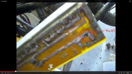
Take a look at this screenshot:Screenshot (126)1.jpg
You mentioned the cap being loose. Is that a hole there? Hard to tell from the video, but that spot looks dark/burnt. Best I can tell, that looks like the negative leg for the bottom cap.
Seeing that the bottom cover on your controller was allowing dirt inside, I would be highly suspicious of the fault being there. And that cap is at the lowest point.


Man I was so tired last night. Fell asleep at the wheel(keyboard) while trying to gather all my photos up. I will be making that update post to my build thread here in a bit.
 
I always got tube pinches and flats with the skinny stock rims and tires, and upgraded to 27/28 and 32mm rims along with heavy tubes and 2.4" "dh" tires. Also softened the susp. So now I'm not looking back for a second (with E especially), but stock was much better to pedal. I had about 15 years pedalling it stock, and the design and capabilities were beyond reproach imo.

Wow, thanks for all the thought on my lil' water snafu!
I am yet to try anything else (still making a list and checking it twice), but your post made me jump up after a long day to see if I missed a cap/cap leg burnt thru the board. No such luck, and prob would have smelled that I guess. It's not loose, but could have leaked electrolyte.
If the cap did go . . . it went quietly . . . into the night :D
(the dark area is just a hole in board with cap shadowing from above. There are other holes of various size in various places also- but good-lookin-out, I thankyou!) 8)

Caps (bottom esp) still on my checklist of course, for all the reasons you pointed out along with extra detail I did not know.
 
That's weird about the hole. It really does look burnt through from the video footage, and it is right there where the cap is. LoL
nutspecial said:
Caps (bottom esp) still on my checklist of course, for all the reasons you pointed out along with extra detail I did not know.
Well I am hoping it is something that simple and cheap. Damage does not look catastrophic.

Have you ruled the battery out yet? Being that the batt output wires are at the very bottom of the controller, I would have expected that to be shorted first.
You might be showing full voltage, but could be cutting out when a load is pulled. I don't remember if you ever said anything about having an onboard BMS?
 
I had a chance to eff around with this today. The battery connections look fine, and there was no evident power issues when calling for amperage.

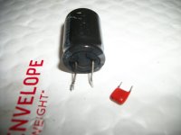
I tried the cap test with the same setting (arrow and T) in the video. Didn't get a reading on old bottom or new caps either. Tried the setting towards the top of MM that looks like two T's turned sideways (for diodes?).

Anyway, decided just to put in the new cap.
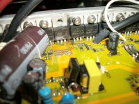
It must have done something, because as soon as I put power to the controller there was a 'pop' and smoke. It came from a new vicinity of two fets and a cap and diode. I pulled the cap and diode as they're all very close together, but visually am having a hard time telling what exactly went 'pop'. I have spare fets and caps. . . but I'm not sure what went wrong, or why the MM didn't work to test.

If a cap's legs touch it's can, or touch a diode cover, I'd imagine that could do it? While replacing the first cap I did notice the cap now in question wasn't glued down, and noted to do so after testing and glueing the bottom one. I may have moved it's legs to rest against the nearby diode or it's own can. Only thing I can think of.

Nothing like thinking a minor repair is going well only to have it compound out of control lol.
Little vid of it.
[youtube]DuGKIaxR_bI[/youtube]
100_1833.JPG
100_1835.JPG
100_1836.JPG
 
Looks like the smoke came out of the fet. Why, I don't know; was the insulator around the screw intact before it was removed? (if not, the tab could short to the heatsink and thru it possibly other FETs and/or board traces/etc., this can blow a fet).

FWIW, if the FET was already damaged for whatever reason, then if it was "on" and so was it's complementary half in another phase, it would read as a short across the battery. It might even not be a complete short at first, but then as power is applied at some point after a failure, maybe not even the first time it's applied, the FET turns fully on and presents a low-resistance path for full battery current...and explodes. :(
 
Lol . . . . Yeah! Thanks Skeetab!

Thanks AW,

The reasoning that it is now a fet and just showing up, doesn't fully sit with me because I cycled the controller many times before deciding to try testing then replace the cap. Unless a blown cap opened the circuit and prevented any power from getting to fets?

I thought fets just switched power for phases, from caps, when calling for motor power?
The 'pop' happened as soon as caps energized.

Still don't understand why fet(s) would blow. I thought they died usually from hard use and heat. It wouldn't match this situation, because the bike just lost all power to the motor just after entering the water.

I did notice there was soot on diode facing the fets though, and there is soot between around those two fets. (no, there were no issues with insulation on screw or behind fet, and definitely nothing was shorting any of their legs).
But although I don't understand why, I think fet replacement (or at least testing) is a safe bet.
Unfortunately, this could get even more 'hairy', as the soldering part is going to become more tedious :|

So, I will look at:
-methods of desoldering 3 pin items,
-methods of testing mosfets,
-find out why I couldn't test the caps,

-and also try to confirm if a cap is prone to blow if it's leg(s) touch it's own can or another component's can. Seems to me there's danger of finding ground thru a component can, right?
That seemed more plausible/likely than fets blowing . . .?


I know some basics, and that's enough to know this shit isn't that complicated or difficult. It's about effin time I gained some proficiency in PCB diagnosis repair.
 
So I've been researching and working on this for like 2hrs . . .

Good things take time

Bad things also can take time :|
_______________________

[youtube]FDuN7QHn1-s[/youtube]
Using this method, I can test caps. The cap charges from continuity testing, and then you measure the dc output, watching it trickle down.
Somehow that's either different, or I misunderstood the first link from Rage.

The removed caps both test fine :!: Also I learned that the cans of components aren't usually grounded, but you still wouldn't want to short the hot leg, or both legs to the can/case.

So the first issue is still a mystery, unless it was fets all along like AW suggests. I don't get why they would blow in that circumstance though.

________________________

[youtube]gloikp9t2dA[/youtube]

Using this method, the spare fets test properly. Of three, they range from about 140 to 240 though. I guess since it's a capacitance test, higher is better?

https://www.utm.edu/staff/leeb/mostest.htm
The source, gate, and drain appear to be uniform on these 4110's, and the same as pictured. I'm not too sure about the bottom paragraph though. I wonder if these mosfets are protected, or if I can know or can trace out any other possibly harmed paralleled fets.
When MOSFETS fail they often go short-circuit drain-to-gate. This can put the drain voltage back onto the gate where of course it feeds (via the gate resistors) into the drive circuitry, possibly blowing that section. It will also get to any other paralleled MosFet gates, blowing them also.
So, if the MosFets are deceased, check the drivers as well! This fact is probably the best reason for adding a source-gate zener diode; zeners fail short circuit and a properly connected zener can limit the damage in a failure! You can also add subminiature gate resistors -- which tend to fail open-circuit (like a fuse) under this overload, disconnecting the dud MosFet's gate.
________________________

Looking into desoldering. . .
[youtube]Z38WsZFmq8E[/youtube]

I got a 'sucker' pump last year after I realized it's pretty much a must-have. Working on these fets though, it would be nice to have smaller tips, and also some of the solder wick stuff.

I overheated the first mosfet and it pulled apart. Then broke all pins so I could focus one each seperately. I consider it a success cuz I didn't mess up the pads- they're so close together with so much solder you have to be really careful. Those three are clean and ready to go.

I am having more success with the 2nd mosfet in question. Try to get all possible solder away from pins and then work them 2 at a time loose and down, care not to overheat the fet.

Extra challenging with rudimentary knowledge and tools.
 
Cool, so I did get the second mosfet out ok, and it tests around 400 VS the spares @ 140-240.

So lower is better right? I'll put the lower-reading ones back in?

I'm about certain that first mosfet was blown. It came apart easily, and looked scorched inside.
The scorch/soot on surrounding components support that too.

But why did it go?
Is there a possible water related cause, even though only the very bottom of the controller could have gotten wet?

What about drivers and paralleled fets?
Are they a concern here at all, and would it be better to wait on reinstalling the two fets, cap, and diode I removed?

Thanks for any input on my 'lil shit-show :wink:
 
Back
Top