QS 205 dropout design

jackal

1 mW
Joined
Aug 10, 2016
Messages
14
Location
Redwood City, CA
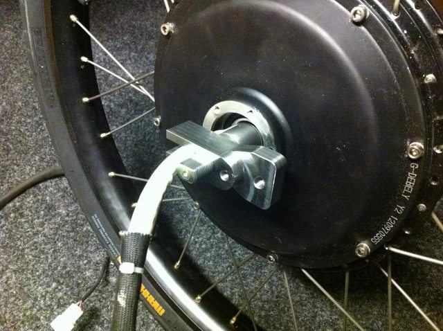
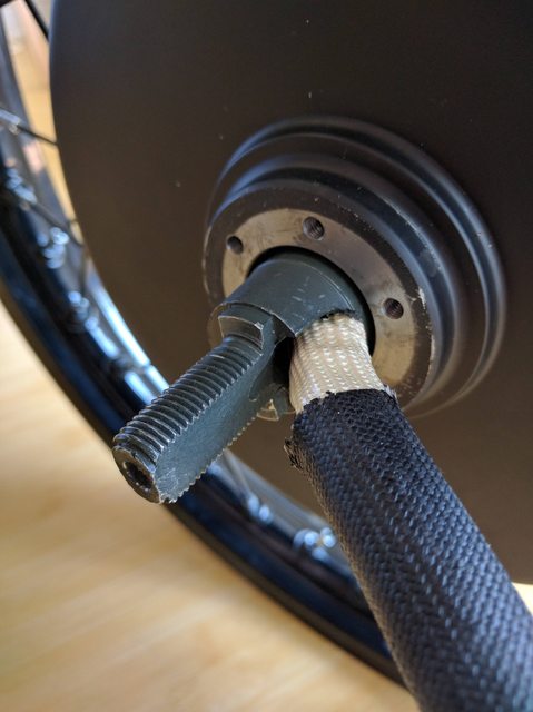
Trying to design the dropouts for a QS205 and came across this issue on the disc side axle. You see, the way it's machined I don't see how you can clamp a flat plate with the nut.

GXkTRPyl.jpg


If you clamp like A, you have good bearing surface but the clamp surface is small and unstable. If you do it like B it's stable clamping but poor bearing

qrL3YFBl.jpg


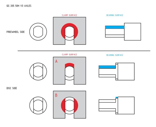
Do you have to use a special washer for A? do you "key" the dropout with extra material in the back? Do you grind the top part in B to increase bearing and clamp surface like the freewheel side?

Hopefully the schematic makes sense
 
https://endless-sphere.com/forums/viewtopic.php?f=3&t=68137&start=25

The end of page 2 is my current attempt to mount one of these motors.
It is a tight squeeze trying to get the huge phase wires safely out of the axle and drop out.
Just not much room to play with.
 
Thanks for the link Icewrench. I see, you are basically building a big clamp for the flat faces of the axle. The nut is almost a secondary complement to tie everything together.
Interesting solution with the "double" version to get the wires out in a reasonable angle. You don't want to bend them too much anyways because the disc will chew it up anyways...
I'm starting to think that this motor should come with a much wider dropout spacing from the factory.
To the drawing board.
 
I used a belt sander to soften the bend on my vector swing arm at the clamp.

It's not enough to weaken the drop out but enough to get the wires out with out problems.

These pictures don't show the second clamping section that bolts on the outside of the arm.

Tom
 
Yeah, that pretty much is the way to go it seems.

Tom, it looks like you are bolting the top part of the second section. Is this to allow the "C" to flex and pinch? you don't want it completely bolted or welded to the other?

I'm also curious as to why you are clamping on the round face of the axle and you are having the wires shooting straight back. I'm sure there's a reason.
 
On a cro motor the wires come out in the same plane as the axle slot.
So the wires only need to make a slight bend to come out through the slot.

The qs50 x 205 wires exit 90 degrees to the axle slot and run smack into the drop out. If you want to use a rear disc brake well mine needed 4mm of shims so the caliper did not rub on the side cover and that eats into wire exit space as well.
Someone recently posted how they mounted their qs with some cnc made parts. But he also did the countersunk screws on the brake rotor. Rotors are made of stainless steel and it will work harden in the blink of an eye. Had a hard time with that till i watched this you tube . https://www.youtube.com/watch?v=NtqXlOX_kF4

haulin colin built a different axle and custom fork to mount up his qs motor.
https://endless-sphere.com/forums/viewtopic.php?f=31&t=78461&p=1208513#p1208513
 
Yes, if the wires came out like this it would help a lot.

EQRjEIWl.jpg


Definitely not an easy motor to work with. If QS is reading this here's some feedback:

- Leave enough space for disc calipers (I think they increased it from 15mm to 17mm in later models)
- Grind the excess material from one side of the axle so we don't have to create pockets
- Make the wire bundle come out "in plane" to avoid extremely tight turns on the cables or grinding ramps in weird places.
 
jackal said:
Yeah, that pretty much is the way to go it seems.

Tom, it looks like you are bolting the top part of the second section. Is this to allow the "C" to flex and pinch? you don't want it completely bolted or welded to the other?

I'm also curious as to why you are clamping on the round face of the axle and you are having the wires shooting straight back. I'm sure there's a reason.

The Vector frames have a second piece of metal that bolts to the frame, I assume this is what your asking about. I think they made a bolt on piece so it's replaceable in case of future upgrades or in case of damage.

If the wires exit towards the front I couldn't put the relief cut in because it would weaken the swing arm and it would make the bend in the wires even sharper. Out the rear is the only logical place in my opinion. When you asked about the clamping the round face that's to keep the wires from touching the brake disk and or disk bolts.

Tom
 
Back
Top