Stromer Mountain 33 Motor & LCD -- Repair / Hacking

amberwolf

Administrator
Staff member
Joined
Aug 17, 2009
Messages
40,735
Location
Phoenix, AZ, USA, Earth, Sol, Local Bubble, Orion
This comes from here:
https://endless-sphere.com/forums/viewtopic.php?f=9&t=86412
The plan, once I figure out how to wire it up, and fix whatever might be wrong with it (or use an external controller if it's unfixable), go on my friend Bill's bike to help him get around a bit easier (or get back home if he's out and can't pedal home).

It's really heavy, though, and he might not want that much extra weight on the bike, so we might have to go with one of the old small Fusin geared hubs I've got instead, but we'll see how this one works out first.

This thread
https://endless-sphere.com/forums/viewtopic.php?f=6&t=63809
and this one
https://endless-sphere.com/forums/viewtopic.php?f=4&t=16742
seem to have the most info about these motors, but I still have to read them (just skimmed so far) thoroughly.

Some pics; don't have time to do or write more at present.
 

Attachments

  • img_4531.jpg
    img_4531.jpg
    52.2 KB · Views: 4,952
  • img_4532.jpg
    img_4532.jpg
    70 KB · Views: 4,952
  • img_4533.jpg
    img_4533.jpg
    55.1 KB · Views: 4,952
  • img_4535.jpg
    img_4535.jpg
    54.3 KB · Views: 4,954
  • img_4537.jpg
    img_4537.jpg
    48.8 KB · Views: 4,954
  • img_4539.jpg
    img_4539.jpg
    51.9 KB · Views: 4,954
  • img_4540.jpg
    img_4540.jpg
    38.3 KB · Views: 4,954
  • img_4541.jpg
    img_4541.jpg
    43.5 KB · Views: 4,953
I couldn't do any other things on my todo list last night, so I tried opening up the motor (since I've gotten no replies in the "hacking a couple stromers" thread about the wiring), to figure out what I might be able to do to test the internal controller by itself.

Having unlaced half the wheel (wire side) I tried to use the 3-jaw puller to remove that half-cover, but not even a tiny bit of movement, and I could see the flange distorting and was afraid I'd snap it off, making it unrelacable.

So I got out the rubber mallet and various flatblade screwdrivers, and started with the thinnest, tapping one into the split seam at about two inch intervals all the way around, then redoing that with the next thicker one, until I got it nearly 1/8" apart.

Still no joy with teh puller, though, so I put a little really thin oil / pb blaster into the seam, and let it sit overnight, then today in teh sun. Again, puller still wont' do it.

Tried it from the non-wire side, same thing.

I'm going to dig out one of my propane torches and try heating it to see if it expands enough for the puller to pop it off, with the puller pretensioned before I start heating. Dunno when I'll get to that though; got other stuff I have to finish first; only had about an hour to play with this so far.

Would be easier if I could find a wiring diagram for the stromer itself, to know what pin needs what signal, so I could fake the signals (or use the LCD if ti works) and test it without opening it up.
 
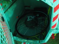
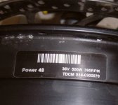
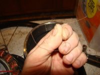
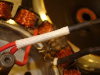
Been sick last two days; worse today than yesterday, coughing, sneezing, runny nose hard to breathe, etc., so didn't get much else done, but I got this motor opened, after leaving it with the oil till this afternoon, sitting in the sun to warm up and expand the aluminum (more than the steel ring inside).

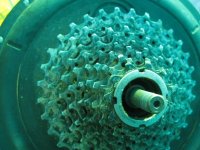
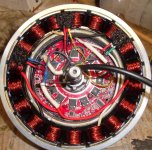
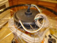
Between fits of sneezing and coughing, and a bathroom trip, first came the side cover, which pulled the whole magnet ring with it (was hoping that would stay in the other side cover :/).
img_4586.jpg
img_4587.jpg


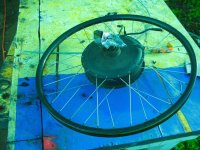
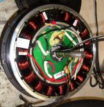
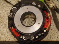
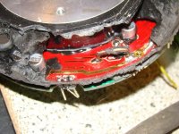
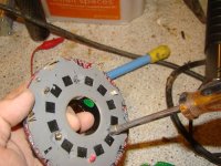
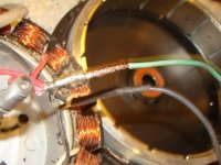
That exposed the controller and stator; this one is one of the potted ones, which will make testing and fixing it harder (if possible at all).
img_4588.jpg
img_4589.jpg

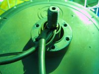
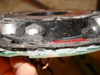
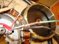
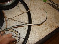
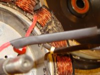
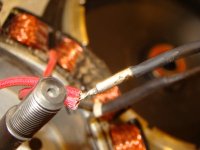
The axle is interesting; rather than a hollow channel, etc., it is simply cut flat for the wires. I don't recall ever hearing of a Stromer with a broken axle, so perhaps this is no worse than a channel cut, or a hollow axle? Of course, there is very little public data about Stromer failures as they are factory bikes with part-swap service, so only the rare instances of "wild" parts or out-of-warranty stuff provide that.
View attachment 14
img_4591.jpg
img_4592.jpg

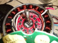
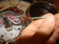
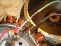
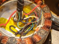
I pulled the other side off the stator, just to see, not much there, but there are 3 screws that hold the controller to the stator, and then 3 other unused but threaded holes, which might be for securing the motor to a fixture for testing at the factory?
img_4593.jpg
img_4595.jpg


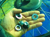
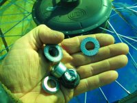
For now that's as far as I can go; am back in bed now resting again, but here's more pics of the insides. It's definitely a couple steps up from the typical "Chinese bike motor", at least in appearance and apparent level of finish.

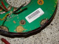
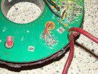
When I got up for a tea-making break in the middle of typing this up, I opened up the display unit while wiating for the tea to boil. I expected to haev to cut it open, that it would be ultrasonically welded or otherwise glued in place, but it is not. the front cover simply snaps right off, and then there are six screws holding a clear stiffener/cover to the back casing.
img_4597.jpg
img_4598.jpg


When that is removed, it takes with it the MCU and the LCD and buttons, leaving a board with what looks like a small voltage regulator similar to that in teh Cycle Analyst v2/v3, and connections for the 3-pin and 5-pin round connector wires to solder to.
View attachment 5
img_4600.jpg
img_4601.jpg


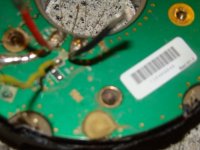
Interestingly these are actually marked for waht they are, whcih I did not expect, and which makes it easier to figure out how to do some hacking.
img_4609.jpg
img_4605.jpg
img_4604.jpg

The 5-pin is marked as:
RX - green
TX - yellow
GND - pink
BAT - blue
PWR_OUT - white

All of these correspond to the 5 wires in the controller on the same type of connector, and most likely all of them go directly to those points in teh wiring harness, as all of those things should go to the controller (or come from it) anyway.


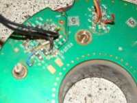
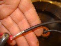
The 3-pin only has two wires inside (the third is cut off at the entrance)
SIN - red
GND - black
Signal IN would be my guess on SIN, probably from the dropout's torque sensor, but I don't know where that 3pin would plug into or go to in the rest of a Stromer bike's wiring harness. Haven't found anything online that shows a wiring diagram I can use.


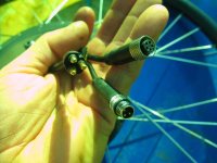
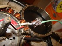
So while that takes care of 5 of the wires in the motor, there are still 8 more.

Two of the large-sized wires on the large 3-pin are certainly battery power; the third wire I don't know what it would be.

Then there is a 2 pin JST, which was heatshrunk off, presumably is either a factory-use-only connector or is a feature connector for an option not installed on the bike this came from.

Last is another 3pin round, but which does not appear to match up to the 3-pin round on the display unit (is different style, colors, etc).

Not sure what it might be for.


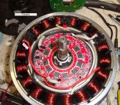
Some thoughts: Stator is pretty wide, as are the magnets. Should be capable of some hefty torque, if enough current was poured into it.
img_4596.jpg


Magnet ring is pretty thick; I'd assume that it is the minimum thickness needed for backiron, as it is rather heavy, and a lighter motor would be better. But if it's too thin there'd be flux leakage and less efficiency, so we'll have to assume they did their homework designing it. ;)
img_4594.jpg

I had a thought while typing the above--I have another motor with wide magnets/stator, that I *think* is the same I.D. as this one. It's that old powerchair BLDC motor. IIRC it has a different number of magnets (more, but smaller), I wonder if this magnet ring would work on that motor, and vice-versa, and what effect that would have? Sort of a pointless thought for now, but my mind wanders like that... ;)
 
I missed a part of this post
https://endless-sphere.com/forums/viewtopic.php?f=6&t=63809&start=50#p966132
where this image
https://lh5.googleusercontent.com/-qIbYqiKGHTo/VFVpsvLkitI/AAAAAAAAsls/dVGPs6wNvdg/w865-h649-no/20141101_190449.jpg
shows a connector for the throttle (can't see which one though) with what look like three black wires (for the throttle) and a white wire. (which appears to be for the brake?).

Haven't found other stuff that shows what those wires go to though. Not even sure that's actually the connector used for a throttle (or if it even has that option).

If there is no throttle option, it's easy enough to fix by using the torque sensor input as a throttle, if it's a constant voltage input of some type. If it's a resistive input, that can be emulated with a potentiometer.


I do wish someone had made a full wiring diagram of a Stromer somewhere, but no luck on that so far. Didn't really expect to find one, though. So when I get the chance I'll get the oscilloscope out, and hook up a battery to the power wires on the motor, with the display hooked up to the motor, and start checking signal lines.
 
I have 2, Stromer 36v500w Power 48 wheels that look very similar, inside and out, to amberwolf's Mountain 33 motors. I finally have a use for them, so I opened one hoping to remove the controller and connect an external controller directly to the motor's phase wires and hall sensors.

I had hope to remove the Stromer controller, but it wasn't easy and just left it inside. I did remove the connection circuit board and the soft silicone potting to photograph the controller. I cut the 3 phase wires and leads to the 3 hall sensors.

Stromer uses Red, White, Black instead of the more common Yellow, Green, Blue for the 3 power wires and the 3 Hall sensors. With trial and error, I sorted through various combinations and found the the one that works properly and turns the wheel forward when connected to an external controller.

Hall: Stromer red-->external controller yellow : white-->green : black-->blue
Power: Stromer red-->external controller blue : white-->yellow : black-->red

I'll be interested in the performance using 36v and 54v with various controller.
 

Attachments

  • label stromer motor.jpg
    label stromer motor.jpg
    64.7 KB · Views: 4,310
  • Motor wiring 4.jpg
    Motor wiring 4.jpg
    117.6 KB · Views: 4,310
  • Motor wiring 3.jpg
    Motor wiring 3.jpg
    91.6 KB · Views: 4,310
  • Motor wiring 2.jpg
    Motor wiring 2.jpg
    129.7 KB · Views: 4,311
  • correct rewire for external controller 1.jpg
    correct rewire for external controller 1.jpg
    149.8 KB · Views: 4,314
Somehow I missed this reply, but found it coming back to update a bit.

Firedog said:
I had hope to remove the Stromer controller, but it wasn't easy and just left it inside.
There are 3 screws on the back of the motor core, they hold the controller puck in place.

The hall leads have to be bent up out of the way.

THe phase wires can simply be pushed to the circumference of the puck as you pull it out.


Update to the status of this is that Bill ended up not wanting a powered bike, and then he moved halfway across the country, so I still ahve this motor.

Right now, I've got the controller removed from it, and will be installing the biggest phase wires I can into it. Then I'll see if I can cut a narrow channel into the other axle, to pass the hall sensors (and a temperature sensor) out. (I don't wnat to run them with the phse wwires both becaus then theyl take up space the phases could use, and because if the phases overheat and mlet insulation tey'd also short with the halls or temperature sensor wires, which can cause more damage to electronisc.

Then this motor, in th 26" wheel, will go into a fatbike fork (that has sufficient dropout width to hold the unmodded axle), which will replace the regular suspension fork and front wheel on the SB Cruiser trike, and I'll have 3WD instead of just 2WD.

Additoinall,y I cna then reroute the chain so it goes up from the cranks to the headtube (on the leftside), then transfers sides via jackshaft (perhaps using an IGH), then to the whee'sl freewheel. If I can, I'll add a derailer to use those gears, too.

I have a few generic basic controllers that should work on this motor, but I"d like to also see if I can find the inductance, kV, and resistance of the motor, so I can test it with the SFOC5 by Incememed.
 
Stromer (if it's the same company; thought they manufactured only commuters) is in San Diego. I used to know a couple of principals since I wrote up a couple of their bikes, but they seemed to have only a sales office there. However, there might be someone who could help with technical issues.
 
Since this is just a motor off such a bike, and I'm not the original owner, I can't imagine they'd provide any help, much less the schematics and technical information necessary to make their motor/controller work on a different bike. ;)
 
I'm adding phase and hall wires to this motor, after having removed it's internal controller puck (cutting the hall and phase wires from it to leave them for this purpose, to keep using the existing hall sensors). I'll run it off a generic external controller, as the front wheel (in a fatbike fork) on the SB Cruiser trike.


The internal puck controller, which I can't make work without the whole system, AFAICT, begged me to expose it's secrets (actually, I just wanted to find out which hall sensor wire was which, *and* which hall sensor is intended to work with which phase, ot make wiring it to the ocntroller simpler--otherwise it'd just be stting in my "whatever" bin...which is where it will go right now).

Here's what I have, so far, in pictures. Some of the pics show pad names, which indicate functions, and may allow hooking the proper LCD/etc to it. I may try this to see if it can be powered up without a Stromer battery (there is a powergood signal from that, which i don't know what it would be, though). But it's only a 350w controller, so probably not of use for the current project, even if I can make it operate, so I won't be spending time on it just yet.

It's actually two circuit boards, stacked, with a few pins sticking out of the actual controller board up into the external connection board (which appears to also be a heat spreader), and soldered together.

Unsoldering those is easy and lets you take the sandwich apart.

Then youc an see the gray semihard silicone potting.

There are three brass standoffs you can undo after removing a bit of the gray potting, which then let you pull off the plastic cover (which I'd already broken up working out how to get this far, not realizing it would be that easy) and heatsink from the other side, exposing soft black silicone.

I simply rubbed off most of the black stuff with my fingers, and lifted up chunks of the gray stuff similarly, and AFAICT no parts came off with any of it.

I *think* the black stuff is not meant to be very thermally conductive, while the gray is, so the FETs in the gray stuff can get their heat out without directly pushing it into the capacitors/etc that are potted in the black stuff.
 

Attachments

  • dsc08182.jpg
    dsc08182.jpg
    55.9 KB · Views: 3,608
  • dsc08181.jpg
    dsc08181.jpg
    37 KB · Views: 3,607
  • dsc08179.jpg
    dsc08179.jpg
    47.4 KB · Views: 3,608
  • dsc08176.jpg
    dsc08176.jpg
    65.7 KB · Views: 3,608
  • dsc08184.jpg
    dsc08184.jpg
    53.8 KB · Views: 3,608
  • dsc08186.jpg
    dsc08186.jpg
    58.2 KB · Views: 3,609
  • dsc08188.jpg
    dsc08188.jpg
    48.8 KB · Views: 3,607
  • dsc08191.jpg
    dsc08191.jpg
    50.5 KB · Views: 3,609
Oh that poor PCB and poor electronics! Gosh that looks like a disaster! And I thought my controller with soldered 10AWG wires all up in the controllers business was messy...
 
This controller is actually very neat, in factory condition.

It just looks messy because of the potting they put in it being only partly removed (I probably never will remove the rest of it; I only needed to find out for sure what the hall sensor pinout was, and was curious about other things. I dont' have enough time to indulge my curiosity completely anymore, or i would do a lot of experiments with this thing).
 
Pics of adding internal phase wires and hall wires for external controller use. Somewhere in there you can see the project supervisors at their jobs. The first pic is just to show veirifcation that the wires would actually even fit in the axle space available, using 16g AC extension cord wires (all I had available right now that was useful) and 7 very small (28g? less?) wires for halls and a thermal sensor (this used to be a serial cable; I stripped off teh whole jacket and shield for the part to go in the axle, using just heatshrink to protect the thin wires, then just past the axle outside the motor resumes the original sheild/jacket. Cable isn't long enough to reach more than partway up the fork but it really just needed to get outside the axle).

I broke the legs off one of the halls so i replaced it with a spare; just superglued it in place nstead of silicone glob like the originals.

Over here
https://endless-sphere.com/forums/viewtopic.php?f=2&t=67833&p=1463761#p1463761
you can see this rear hubmotor mounted on the trike's front (fatbike) fork (just had to bend the fork wider a few mm).
 

Attachments

  • dsc08214.jpg
    dsc08214.jpg
    54.8 KB · Views: 3,571
  • dsc08209.jpg
    dsc08209.jpg
    49 KB · Views: 3,571
  • dsc08207.jpg
    dsc08207.jpg
    45.2 KB · Views: 3,570
  • dsc08206.jpg
    dsc08206.jpg
    37 KB · Views: 3,569
  • dsc08205.jpg
    dsc08205.jpg
    60.3 KB · Views: 3,570
  • dsc08216.jpg
    dsc08216.jpg
    44.1 KB · Views: 3,570
  • dsc08217.jpg
    dsc08217.jpg
    38 KB · Views: 3,570
  • dsc08221.jpg
    dsc08221.jpg
    42.1 KB · Views: 3,570
  • dsc08224.jpg
    dsc08224.jpg
    30.2 KB · Views: 3,571
  • dsc08234.jpg
    dsc08234.jpg
    48.9 KB · Views: 3,573
  • dsc08228.jpg
    dsc08228.jpg
    67.8 KB · Views: 3,572
  • dsc08227.jpg
    dsc08227.jpg
    49.3 KB · Views: 3,572
  • dsc08226.jpg
    dsc08226.jpg
    32 KB · Views: 3,571
  • dsc08225.jpg
    dsc08225.jpg
    34.6 KB · Views: 3,572
Pics of it mounted on the trike, though it's not yet wired to a controller.

https://endless-sphere.com/forums/viewtopic.php?f=2&t=67833&p=1466757#p1463761

file.php


file.php


file.php


file.php


file.php
 
I was looking at the label on the motor with the "TDCM", and it occured to me that perhaps TDCM made the motor controllers for these. So I poked around the web, and found this page
tdcm-motor.com/products/oem-motor-production/
whcih has this image
OEM-495x400 (1).jpg
which is *clearly* this style of UltraMotor on an assembly line. :)

That made it likely that TDCM actually made these UltraMotors, at least the ones on Stromers with the label like the one in this thread.

Further poking found this
https://electricbikereview.com/forums/threads/need-help-with-my-stromer-sport.16229/
which has a post by Bluecat that says
Interesting; I thought, A2B was a trademark of UltraMotor. Then it seems as Ultra Motor ran into bankruptcy, their business was taken over by TDCM.


While I'm linking stuff, here's a similar thread on opening up an Ultramotor (from an A2B)
https://endless-sphere.com/forums/viewtopic.php?f=2&t=30050
 
I forgot to post this, but I've been using this motor in a 20" wheel on the right rear side of SB Cruiser, after apparent internal short of the MXUS 450x that seems to have blown the generic controller I'd been using.

I'm using it with another generic that seems to be a simulated sinewave type, and ti's almsot completely silent except around 10MPH or so, where it begins grinding and grumbling--once past that, its' fine again up to 20MPH where my limit is.


It heats up pretty quickly when it's being used for braking (30C+ increase each time, even if only a second or so). Not nearly as bad during acceleration, but it does get toasty trying to push the trike around, even with the help of the other motor (MXUS 450x) on a Grinfineon 30A. I can't remember the current limit on the generic controller running it,but I think it's about 40A.
 
Back
Top