How do I wire dual motor e-brakes like this?

pwd

10 kW
Joined
Oct 11, 2011
Messages
799
Location
Ontario, Canada
Hello ES

Its almost what I call soldering season again. I will be adding a second motor + controller to my latest e-bike. Both brake levers will just have a basic magnet sensor to trigger regen braking. My plan is to have the front brake lever control the front regen and the rear level control the rear regen. I have done this in the past with two motors but I would like to improve the behavior by ensuring both motors are off or without throttle when either of the brake levers are pulled. The catch is that I only want the e-braking to happen on the lever I pull; but I need both controllers to cancel their throttle signal.

Any ideas?
 
So you only want regen to happen on the side that got pulled?

How about two switches on each lever. One closes the regen/eabs circuit. The other acts as a brake. You wire the brakes outputs and controller inputs all in parallel. Regen switches go to separate controllers.

Only works if controller can read the eabs circuit closing in real time vs reading it on power up. I don't have wheels that can do regen, so no experience to tell if the above would work, but if you get an extra magnetic sensor, you can test.
 
Alternately, use a single switch on each lever, and drive a separate relay with each one.

Use a (DPDT) relay with two sets of both a NC and NO contact, so you can use one set of one type of those for the ebrake on that motor, and then the other set with the opposite type will go between the 5V line from that motor's throttle to the power.

If not using independent throttles, it might get a bit more complex to do.
 
If not using independent throttles,...
That's kinda of what is running thru my mind.
Do you really need to run both motors all the time?
I don't intentionaly and my motor systems are less powerful than yours
Except for quick take-offs and top speed runs, I stay on the rear motor only.
My independent throttle are together on the left side;
100_0028.JPG
100_0029.JPG
Half-twist next to a thumb, very natural to use.
But most of the time, I use PAS for the rear and add w/the thumb(frt. motor).
Ebrake only on the rear motor since the frt. is throttle only..
 
Yes, that solution works if the controllers are up to it as motomech said - most should work as described. For the record, I think regen on front wheels is a bad idea unless you meticulously preflight it like a pilot every time you ride or have something like Dr. Bass' setup where he used a 20mm through axle. What kind of front axle setup are you going to use?
 
Thanks for the suggestions everyone. I forgot to mention that both controllers will handle disable the throttle when they receive the brake signal; so that part is already functioning. I just need it to send a very short brake signal to the opposite controller when either of the brake levers are used. The front controller is a Magic Pie 4, and the rear will be an em3ev Infineon 12 FET IRFB3077.

@ecycler - I've been using front regen for a few years and as long as it is dialed down; it works great. The Magic Pie 4 is only set to 40% regen; so its not too overpowering. The axle is just the standard Magic Pie axle @ 14MM.

@motomech - Thats a nice setup; but in my case I've already got a throttle wired for handling two controllers and my handlebars are completely full already.

@amberwolf - It sounds like a good solution. I will have to brush up on my electronic competent knowledge; but some sort of relay was what I had in mind.

I will have to do some testing but does anyone know if the +5vdc for the throttle will always be present; even when on the ebrake?
 
I will have to do some testing but does anyone know if the +5vdc for the throttle will always be present; even when on the ebrake?

Yes.
 
Watch out for ground loops on any setup where two power systems are being combined.

Dont fall into the trap of one throttle two controllers.... its problematic
Avoid two throttles on the bike... its hard to control under power

Run a dual-hall throttle.
One throttle, two independent outputs
One output can be trimmed with a standard POT if you want a differential to ensure front traction

As for brakes... I always ended up moving toward using high end independent hydraulic brakes... then a button for regen.
Hydraulic brakes give you feather control.... regen is almost always funky unless it is variable... and even then you are likely stuck with a Chinese lever.
If the regen must be variable... i would use something like a thumb throttle to activate it.

When riding efficiently... use nothing but the regen lever to hyper-mile
When running agro-crazy.... forget the regen and just use your real brakes.... as the inefficiencies involved eclipse any regen savings at least 10:1

Street data - not speculation.
30+ ebikes built and run into the ground

-methods
 
ecycler said:
I will have to do some testing but does anyone know if the +5vdc for the throttle will always be present; even when on the ebrake?

Yes.

Thank you for the confirmation.

methods said:
Watch out for ground loops on any setup where two power systems are being combined.

Dont fall into the trap of one throttle two controllers.... its problematic
Avoid two throttles on the bike... its hard to control under power

Run a dual-hall throttle.
One throttle, two independent outputs
One output can be trimmed with a standard POT if you want a differential to ensure front traction

As for brakes... I always ended up moving toward using high end independent hydraulic brakes... then a button for regen.
Hydraulic brakes give you feather control.... regen is almost always funky unless it is variable... and even then you are likely stuck with a Chinese lever.
If the regen must be variable... i would use something like a thumb throttle to activate it.

When riding efficiently... use nothing but the regen lever to hyper-mile
When running agro-crazy.... forget the regen and just use your real brakes.... as the inefficiencies involved eclipse any regen savings at least 10:1

Street data - not speculation.
30+ ebikes built and run into the ground

-methods

I have been using the one throttle two controllers route on my previous bike and its been working but it does suffer in the response department; which I understand is where the dual-hall throttle come in. I have read your post regarding the dual hall throttle : https://endless-sphere.com/forums/viewtopic.php?f=2&t=12356&start=169 and that seems like a brilliant solution; I wish there was an off the shelf system like that. I dealt with the front traction issue by reducing the Magic Pie's acceleration to around 50%; but I do like the POT idea.

For my brakes; I'm actually using a hydraulic front and mechanical rear. I am just using those inexpensive magnet e-brake sensors to trigger the e-brake signal to the controller. I like the feel of the regen kicking in first when applying the brakes; then if I need more stopping power I just pull harder. Regen will be dialed down in the front and close to full regen in the rear. The street data is valuable though, especially with that many ebikes :twisted: haha Thanks for the input.
 
A bit of an update that opened up some more questions. I have decided to keep it simple and just have the left brake control the rear motor and the right brake control the front motor. Now on to typical dual drive challenges ...

I've fabri-cobbled the dual hall throttle as methods has suggested; mine is alot uglier though. I had an old Golden Motor throttle laying around and I used the throttle hall sensor from that unit. The GM unit had a couple of extra leads coming from the hall sensor which I think were used to power a battery level indicator; so it doesn't fit as nicely as a sensor from a throttle with just 3 wires.

The the primary hall sensor reads slightly higher as methods has nicely outlined. My issue is that it actually had the opposite bias I was hoping for. I don't have the exact readings on me but the front motor is using the secondary hall (the one I added) and the rear motor is using the primary hall (the sensor that was already in the throttle).

When I twist the throttle, the front motor reacts a lot sooner than the rear. I was expecting the motor connected to the primary hall sensor to react first :? I should also note that the front controller is a Magic Pie 4 (sine-wave) and the rear is an em3ev Infineon 12fet 3007.

As a result; the front motor spins out constantly. What size of resistor could be added to correct the throttle bias between the front and the rear? Also, will adding some extra resistance to the throttle signal affect the top speed of that motor?

Thanks guys, here is a shot before I got it rolling:

oLBXn5R.jpg
 
pwd said:
As a result; the front motor spins out constantly. What size of resistor could be added to correct the throttle bias between the front and the rear? Also, will adding some extra resistance to the throttle signal affect the top speed of that motor?
Adding resistance won't, but that also wont' do what you want.

Scaling the voltage will do what you want, but will also limit the top speed.

So what you can do is wire a potentiometer with it's center lead to the controlller's throttle signal input, it's top lead to the throttle's signal output, and the bottom lead to ground. THen adjust the potentiometer until the controller does things the way you want at startup.

Then if you need an override for a higher top speed, you can add a switch or button that siimply shorts the top lead and the center lead of the throttle.
 
Forgive my ignorance; but can you explain why adding a resistor won't do what I want? I'm on board with your solution; I'd just like to understand the reasoning.
 
If you put the resistor in series from throttle output to throttle input, it will drop different voltages depending on how much current is flowing at the time. If the current is constant then I suppose it might work, if you use the right resistance to drop the right amount of voltage.

If you put the resistor from throttle output to ground it might work by bypassing some of the current if the resistance is low enough (but not too low).


I haven't measured the current flow into or out of a throttle signal line before, but I'd guess it's very low.


If you were using a potentiometer throttle rather than a hall throttle, then adding a resistor in series with the power input to the throttle could work, (and/or in series with the ground) but hall throttles don't work the same way.


The potentiometer trick has been done before, so we already know it'll work.


You can also use just a two-resistor voltage divider in place of the pot, once you use the pot to determine the proportions between them that make the system do what you want. One resistor = the top half of the pot, and the other = the bottom half.
 
Thanks for the explanation amberwolf. That's very helpful. 8)
 
PWD-
I like your choice of a bike, color too! Were you looking for a nice big, open triangle or just being patriotic?
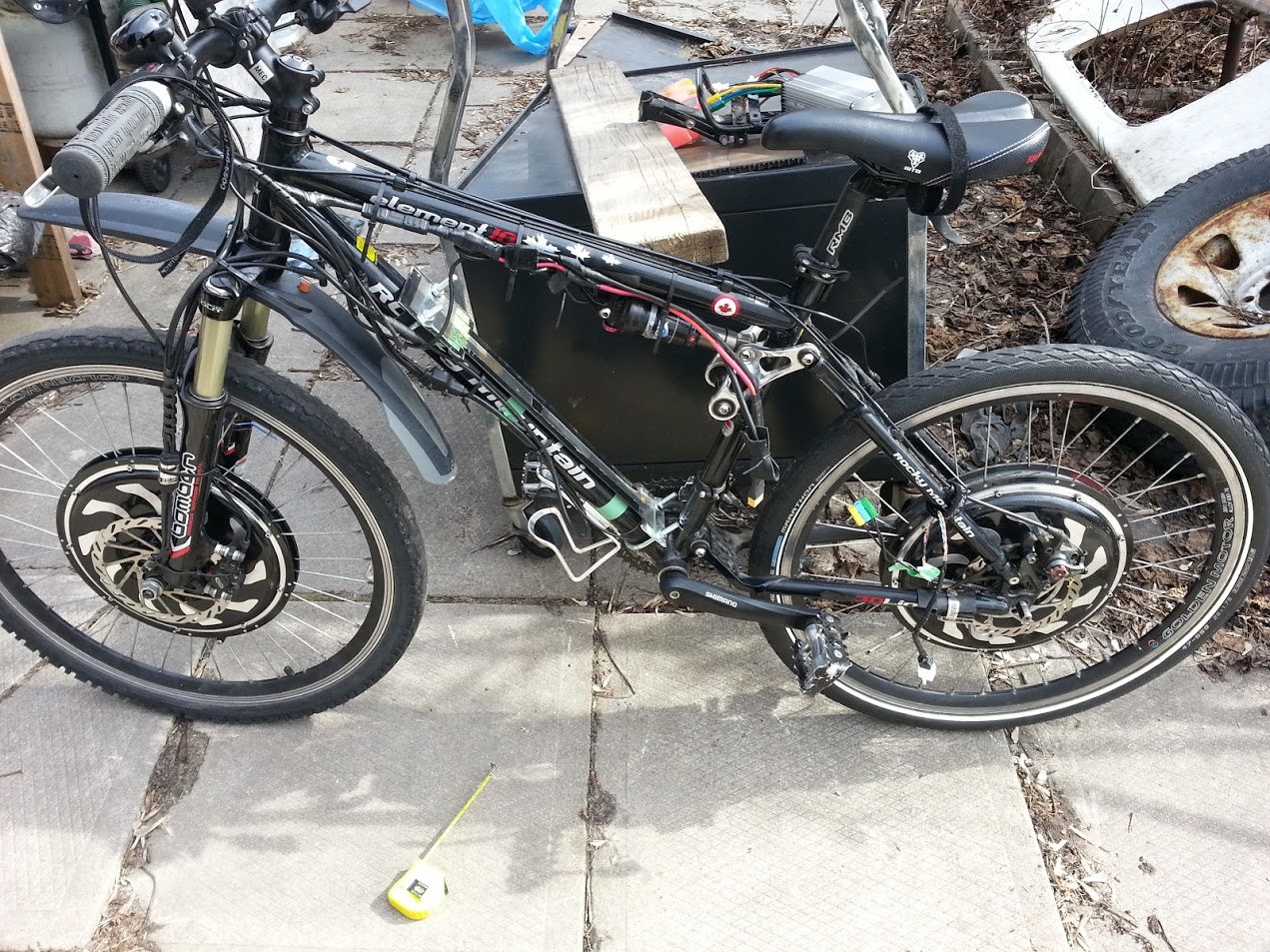
I luv my 2003 Edge. It's basicly out-fitted w/ the same components as a '05 Element 30, but w/ 130mm Bombers and 4.75" Float R;

100_0073.JPG

The way I got it is kinda funny. In 2010, I was in this huge bicycle "superstore" looking for a bike for my first build when I spied this bike all dusty sitting in the corner and asked the salesperson about it. "Oh, it had been lost in the warehouse, we just found it." I offered them a $1000 and they took it.
It's a XL (20.5") frame, and while that is great for packing in the batteries, I couldn't straddle the top tube w/out it intruding into my,....personal space. So I laced up some 24"(wider)wheels, but then I would get pedal strikes in the corners. Eventually, I replaced the crank-set w/ one that came w/ a 50T chain ring and shorter crank arms.
The bike has been "solid as a rock", and the only non ebike things I've had to do revolved around the shock. The seals had dried-up from sitting for 7 years and I put a rebuild kit in(super easy)and while I was at it, i installed a Fox Air-Volume Tuning Kit in it. I'm 200 Lb.s+, an w/out much progression in the 3D Link, if the pressure was set to be soft for the street, the travel got used up quickly(although it has never bottomed out). The kit includes 3 plastic pieces that look like carburetor floats. One is installed in the shock body and reduces the air volume, and the result is the shock feels more progressive, adding more resistance toward the end of it's stroke. Once or twice a year, I put some drops of oil into the shock thru the Shrader valve to keep the seals soft. Usually, I have to add air every 2 weeks or so and rather than use the laborious hand pump, I use a CO2 tire inflator. Try as I might to be careful, it''s hard not to over-charge the shock, probably why this is not recommended. But I have been doing this for a couple of years w/out damaging the seals.
About the only thing neg. I would say about my Edge is, it's not really a great "pedaler", but I have a single mini-motored GT Idrive(another great bike) for that.
Sorry 'bout running on about my Rocky Mountain, it's just I don't see many here, and for my usage, there really isn't anything newer that I would want to replace it with.

P.S., To keep things neat, I have everything in the frame bag, all the connectors, 2 big controllers and batteries, 20 Ah of LiPoly, plus another 5Ah in the tube on the frt. down-tube. About 40 miles range. Having 2 throttles allows me to run only one motor most of time and that extends the range.;

100_0064.JPG
 
I've just realized that I think I wired up the throttle connectors opposite of what I wanted to accomplish which probably explains why the front motor starts before the rear motor...

Here were my measurements from when I finished the dual-hall throttle:

Off voltage:
Primary: 853mV
Secondary: 943mV


WOT voltage:
Primary: 3.611V
Secondary: 3.579V

I had incorrectly assumed that the primary hall would have a higher "idle" voltage but that's not the case. So, I put the rear motor on the primary sensor and the front on the secondary sensor but I should have done the opposite. For reference, here are the readings from the throttle methods built:

Off voltage:
Primary: 813mV
Secondary: 926mV
Threshold: 1.2V

WOT voltage:
Primary: 3.56V
Secondary: 3.48V
Threshold: 3.14V

Bias: 5% toward the rear

his results are nearly identical to mine. I misread both voltage tests :oops: I'd better head back to the workbench. I do have a question about his results though, does the Threshhold measurement represent when the controller starts/stops responding to the throttle signal voltage?


@motomech
thanks for sharing - you've got a nice setup there. I don't have many kms on mine (probably under 500) but so far my Rocky Mountain feels very reliable. Its the nicest bike I've owned.
 
pwd said:
I do have a question about his results though, does the Threshhold measurement represent when the controller starts/stops responding to the throttle signal voltage?.
Probably, given that those numbers look like the ones I've seen printed on controllers for their throttle response range.
 
I just came back from a short ride and for the first time in a while; I had a blast with my bike :D I wanted to share my observations.

em3ev Infineon 12fet 3077 (used on a rear Magic Pie 2):
I'm absolutely loving this controller; its easy to program and has good features. I've got the LVC on the controller set to 48.5V; which prevents me from abusing my battery when it approaches the bottom of the charge. It cut power immediately when my Cycle Analyst showed 48.5V (I was accelerating fairly hard). The regen works great; I have it on the strongest setting; although it would be nice to make smaller adjustments. The Magic Pie 2 works well with this controller; it was previously used with the integrated Magic Pie 2 controller. I am happy with this upgrade.

Magic Pie 4 front (Golden Motor Canada):
I love how silent and smooth this motor is; quite the improvement from my original Magic Pie 2. I have acceleration set to 80% because the wheel will just loose traction; especially because I am running 2WD. I've used this motor by itself on the same bike for a year and it performs well. It makes for a clean install since the controller is built in. The regen works well on this motor/controller. I have turned down regen since I found the maximum setting too strong for my style; I can't recall what value I'm using at the moment. I applaud the low voltage behavior on this one; as you reach the LVC value; it reduces throttle response to limit power draw; so you can still get moving. I haven't tested to see if it completely shuts down when the LVC value is reached but I'm sure it does.

em3ev 14S5P 30Q pack:
I purchased this battery over a year ago as I wanted to move to something more convenient than my previous setup. I haven't seen inside but the build quality is excellent. This pack uses an aluminum case which makes for some nice armor and prevents water ingress. Performance wise; this thing delivers. With 2WD on my bike; I'm sure glad I chose the 30Q cells. My cycle analyst show a max current of 67 amps. I usually do shallow cycles to prolong the life of this pack; but I'm very happy with it. The XT90 anti spark connectors are a nice touch; I didn't realize it came with these; I was expecting the the triple Anderson PP connectors; its much cleaner with the xt90s.

My bike works well and rolls along nicely on my Rocky Mountain frame. This setup has breathed new life into my e-bike experience. Thanks to ES; I've got it close to perfect; it will never be finished though :wink:
 
Back
Top