PAS sensor on SRAM 1-11 drivetrain Cranks?

Joined
Aug 25, 2011
Messages
212
Hello All,

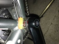
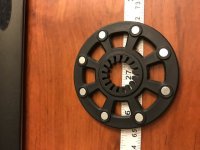
I bought a Q128cst system and had it laced to a 700c wheel. I started working on the install today and ran into an issue with the PAS sensor install. The problem is I have a holotech type splined crank and bottom bracket. The PAS magnet wheel is is set up for a square drive with a gap for the PAS wheel to reside. My problem is I dont have any space betwen bottom bracket and my crank. Also the large spline woudl requre me to dremmil out the fingers on the PAS wheel to fit. I dont mind trying this, but curious if I can sandwich the PAS wheel between the crank and BB? I am sure man have had this same issue and curious how people resolved it. Also moving the PAS Setup to the drive side would not do much as I only have a single chainring so cant mount the PAS wheel to one of the ring spiders.

Here are some pics of what I have. I am open to any advice and also open to buying other items if needed to make this work on the non drive side if possible.
 

Attachments

  • IMG_2696.JPG
    IMG_2696.JPG
    53.3 KB · Views: 1,263
  • IMG_2697.JPG
    IMG_2697.JPG
    44.1 KB · Views: 1,262
The technical requirements are that the magnet poles are oriented properly to the sensor, and cross the sensor in the right direction. So you can put the disk on the side where it best fits and use any method to mount the sensor.

If there's enough plastic, dremel the disk. If you have to glue it to the axle, make sure the PAS works first.
 
Perhaps it's time to "Ask Dave".
Dave always knows;
https://endless-sphere.com/forums/search.php?keywords=hollowtech&terms=all&author=D8veh&sc=1&sf=all&sr=posts&sk=t&sd=d&st=0&ch=300&t=0&submit=Search
 
Hello all,

Thanks for the reply and clarification on things. My bike is an SRAM 1x11 setup so before I buy any new parts I think I may have a solution. I dont have the small chain rings to attach the PAS ring too, but I do have the spider arms in a 5 legged array (72 degrees). I think I can cut out the center part of the ring and either glue it to the 5 legs or if needed 3D print an adapter to place the PAS ring in an optimal position and glue the adapter in place. As for the air gap between magnet and sensor, can you give me a range? Does it need to be close in the 1mm range or can I get away with 6mm or so or even more? I dont have my battery yet so cant test it beforehand, but if I had an air gap range to shoot for I can at least get everything set up in advance.

Your thoughts?

Marc
 
Hello All,

I figured out how to get my PAS sensor mounted to an Isis splined Crank. Unsure if this will work for others, but below is some info on how I made it work.

I have access to a small 3D printer at work so I designed up a few items to help adapt the PAS Magnet ring. I had to dremmil out the internals and decided on my first try to make an adapter to hold the Magnet ring and use Orings to hold it on. This would have worked fine, but the ears for the orings touched the crank spider a bit too high and the magnet ring hit the PAS sensor before the crank was tightened down.

View attachment 7 IMG_2698.JPG IMG_2699.JPG

Unfortunately this was a no go, but it was good enough for me to use as a guide to see what spacing i needed. I surmised that I could not use an adapter at all and the ring must glue directly to the spider to give proper spacing. I figured I could design a fixture to slide over the Isis crank tube and then hold the modified PAS Magnet ring concentric to the tube. Below are a few pics of the adapter I made that show how it worked.

IMG_2702.JPG IMG_2704.JPG IMG_2705.JPG IMG_2706.JPG IMG_2708.JPG

There is a chance this still may run backward and if so I will just flip the PAS sensor block around since its held in with a single screw. If that does not work, I can flip the ring and change polarity. Its lightly glued for now and I will glue it in more securely once i know it works. I pick up my battery Friday so shoudl have this going soon.

Best regards,

Marc
 
Back
Top