DIY Custom Conttroler Version 2

glenn0010

100 W
Joined
Jul 1, 2015
Messages
117
Location
Mgarr, Malta
Hi Guys,

I have a thread where I created the first really expensive bulky version of a brushless motor controller but it worked.

[youtube]0XuylPevH7s[/youtube]

The thread can be found here : https://endless-sphere.com/forums/viewtopic.php?f=3&t=70870&start=75

Now I want to move on to version 2. I will be doing this for my final year project (Bachelor's Degree in Electronics and Control Engineering) My main aim is to make the circuit compact and cheap and also add current and temperature control.

In my first controller I used isolated DC/DC converters for the mosfet drive. However these were 6 Euros each (x6 =36euros) so that is quite expensive. In the second version I would like to use IR2113. I have never used this configuration before so if anyone has some tips they would be appreciated.

I know that you can not run 100% duty cycle using the gate drives, however for a BLDC controller one of the phases has to be off at any given time so hopefully the capacitor has enough time to charge and hopefully can give me 100% duty cycle when it is required to be on. I am going to use a switching frequency of 30kHz and below is the circuit diagram

Capture1_zps3qrwvmro.jpg


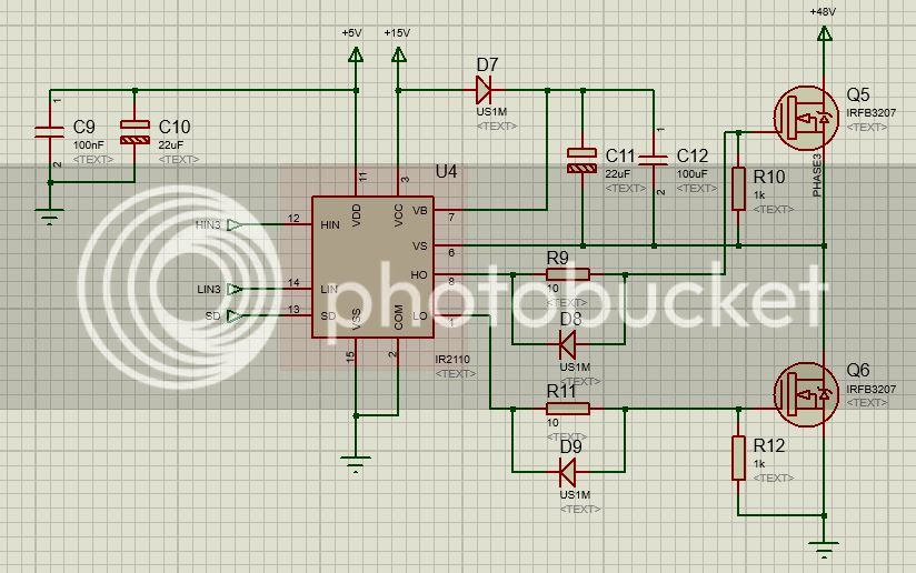
I think I have sized the drive capacitors appropriately for the switching frequency correct?
I also plan on testing the circuit and then adding a snubber circuit to remove voltage spikes.

Any feedback?
I plan on starting this project in about 2 months after I finish this semester.


Regards Glenn
 
Would be great if you could do something like VESC: http://vedder.se/
 
casainho said:
Would be great if you could do something like VESC: http://vedder.se/

I've actually looked at this before.

To be honest this thing is a work of art. I am not on his level yet. Mostly when it comes to the communications protocol as I've only used UART so far. Also this thing uses Field oriented control (FOC) which is quite difficult to implement and you need a lot of computational horsepower.

My main aim is to focus on good hardware design and include features which would be useful for Ebike such as and LCD scree (similar to cycle analyst). I also plan on working with sensored motors so far. I plan on using the LPC2119 ucontroller (ARM7).

Once I fish my current plans I will obviously look forward to improving it mand make it better than his possibly but that is a long way off in the future :p

Regards
 
I did choose a different path (on this days, but about 3 years I go I also tried to make my own controller), to make firmware for the cheap and wide available EBike controller BMSBattery S series controllers, that use the well known STM8 controller -- see here the project: https://endless-sphere.com/forums/viewtopic.php?f=2&t=87870

And I also just finished FOC firmware for electric unicycles: http://forum.electricunicycle.org/topic/1109-firmware/?page=41#comment-90781
 
casainho said:
I did choose a different path (on this days, but about 3 years I go I also tried to make my own controller), to make firmware for the cheap and wide available EBike controller BMSBattery S series controllers, that use the well known STM8 controller -- see here the project: https://endless-sphere.com/forums/viewtopic.php?f=2&t=87870

And I also just finished FOC firmware for electric unicycles: http://forum.electricunicycle.org/topic/1109-firmware/?page=41#comment-90781

Wow man really well done. You definitely know your programming.

That is the beauty about these websites that everyone creates the own stuff. After I finish my current plans. I will try to add FOC but you need to know a precise angle of the rotor correct using an encoder. Hall effect sensors are not accurate enough for FOC right?

I also used the STM32F4VG07 last summer briefly but it didn't have the time to learn it correctly and I much more comfortable with the ARM7 LPC2119 microcontroller.
 
glenn0010 said:
I will try to add FOC but you need to know a precise angle of the rotor correct using an encoder. Hall effect sensors are not accurate enough for FOC right?
I am doing FOC (a modified version) using hall sensors - and angle interpolation between the 60º of hall sensors signals and I have 1º of resolution. The unicycles all of them have hall sensors. Maybe in future I will try to develop the sensorless algorithm. But I use A LOT of OpenSource, I would not be able to do it without using OpenSource projects like Shane Colton documentation and firmware, as also VESC.

glenn0010 said:
I also used the STM32F4VG07 last summer briefly but it didn't have the time to learn it correctly and I much more comfortable with the ARM7 LPC2119 microcontroller.
I used before some LPCs and others also, like Atmel, etc. STM32 have a nice PWM and ADCs for motor control, including FOC. The nice is that the cheap STM8 also have the same for motor control... but even nice thing is that STM32 and STM8 are really cheap!!!! that's why we found them on electric hoverboard, ebikes and unicycles controllers - also on the most cheap Ebay dev boards of $1!!! I am adapting myself to the already existing and popular controllers/hardware.
 
casainho said:
glenn0010 said:
I will try to add FOC but you need to know a precise angle of the rotor correct using an encoder. Hall effect sensors are not accurate enough for FOC right?
I am doing FOC (a modified version) using hall sensors - and angle interpolation between the 60º of hall sensors signals and I have 1º of resolution. The unicycles all of them have hall sensors. Maybe in future I will try to develop the sensorless algorithm. But I use A LOT of OpenSource, I would not be able to do it without using OpenSource projects like Shane Colton documentation and firmware, as also VESC.

glenn0010 said:
I also used the STM32F4VG07 last summer briefly but it didn't have the time to learn it correctly and I much more comfortable with the ARM7 LPC2119 microcontroller.
I used before some LPCs and others also, like Atmel, etc. STM32 have a nice PWM and ADCs for motor control, including FOC. The nice is that the cheap STM8 also have the same for motor control... but even nice thing is that STM32 and STM8 are really cheap!!!! that's why we found them on electric hoverboard, ebikes and unicycles controllers - also on the most cheap Ebay dev boards of $1!!! I am adapting myself to the already existing and popular controllers/hardware.

Yes it's true. You can definitely use stuff that's already available to help you along. I didn't use FOC for my first version of the controller. In all honesty I don't really know how it works so I have to look it up.

Yeah the beauty about these micros is that they are really cheap and powerful and they are pretty much limitless.

It's definitely a good idea to use what already is used. Maybe after I finish V2 I will switch to the STM8 and use FOC
 
Note that STM32 is the really most powerful!! not STM8. For instance, the STM8 don't have DMA while STM32 does, etc. The STM8 on cheap ebikes controllers can't do FOC, just sinewave.
 
casainho said:
Note that STM32 is the really most powerful!! not STM8. For instance, the STM8 don't have DMA while STM32 does, etc. The STM8 on cheap ebikes controllers can't do FOC, just sinewave.

Yes the STM32 is 32 bit, and STM8 is 8 bit. How did you generate the sinewave did you use a lookup table? it would be interesting to implement it for my application since I am driving my motor with just PWM like a DC motor (modified square wave).

Thanks
 
Lookup table, STM32F103 do not have FPU and so trigonometric math is really slow. And I bet original firmware do like that also.
 
casainho said:
Lookup table, STM32F103 do not have FPU and so trigonometric math is really slow. And I bet original firmware do like that also.

Hmm that's really interesting. What mosfet drivers did you use? I saw that on the VESC he was using he DRV3208 which is a really nice IC since it has integrated BUCK converter, drivers and current sensing. It is however a bit too complex for my needs as I prefer to do things with dedicated ICs for now.

I plan on using the IR2308 as it has integrated dead time of around 500ns.

 
Well, the board I am using also uses that kind of ice and I really like because is a cheap e easy to repair and understand the technology.

Please give a look at the simplified schematic of my board and the components used: https://eggelectricunicycle.bitbucket.io/MicroWorks_30B4_board.html

This boards work with 60v and not so much current as EBikes, at least looking for the MOSFETs dissipators.
 
casainho said:
Well, the board I am using also uses that kind of ice and I really like because is a cheap e easy to repair and understand the technology.

Please give a look at the simplified schematic of my board and the components used: https://eggelectricunicycle.bitbucket.io/MicroWorks_30B4_board.html

This boards work with 60v and not so much current as EBikes, at least looking for the MOSFETs dissipators.

Wow nice job!! You are using the IR2148 and it has only 1 input signal which truns the high mosfet on and the low mosfet off. When you are applying PWM to the mosfets wouldn't it be switching on 2 phases with the PWM? I see some people using this Driver but I can't figure out how they do it with only one input per driver. Since when you are applying PWM you could be switching both high side and low side mosfets on of 2 phases correct?
 
I am using center aligned PWM, for Space Vector Modulation <--- search for this keywords on google or see this videos and documentation: https://eggelectricunicycle.bitbucket.io/FOC--Texas_Instruments_videos.html

My PWM setup:

#define PHASE_A_HO_LO__PIN GPIO_Pin_1
#define PHASE_A_HO_LO__PORT GPIOB
#define PHASE_B_HO_LO__PIN GPIO_Pin_0
#define PHASE_B_HO_LO__PORT GPIOB
#define PHASE_C_HO_LO__PIN GPIO_Pin_6
#define PHASE_C_HO_LO__PORT GPIOA
#define PHASE_A_SHUTDOWN__PIN GPIO_Pin_2
#define PHASE_A_SHUTDOWN__PORT GPIOB
#define PHASE_B_SHUTDOWN__PIN GPIO_Pin_7
#define PHASE_B_SHUTDOWN__PORT GPIOA
#define PHASE_C_SHUTDOWN__PIN GPIO_Pin_5
#define PHASE_C_SHUTDOWN__PORT GPIOA

void pwm_init (void)
{
GPIO_InitTypeDef GPIO_InitStructure;

// mosfets drivers pins
GPIO_InitStructure.GPIO_Pin = PHASE_A_SHUTDOWN__PIN;
GPIO_InitStructure.GPIO_Speed = GPIO_Speed_50MHz;
GPIO_InitStructure.GPIO_Mode = GPIO_Mode_Out_PP;
GPIO_Init(PHASE_A_SHUTDOWN__PORT, &GPIO_InitStructure);

GPIO_InitStructure.GPIO_Pin = PHASE_A_HO_LO__PIN;
GPIO_InitStructure.GPIO_Speed = GPIO_Speed_50MHz;
GPIO_InitStructure.GPIO_Mode = GPIO_Mode_AF_PP;
GPIO_Init(PHASE_A_HO_LO__PORT, &GPIO_InitStructure);

GPIO_InitStructure.GPIO_Pin = PHASE_B_SHUTDOWN__PIN;
GPIO_InitStructure.GPIO_Speed = GPIO_Speed_50MHz;
GPIO_InitStructure.GPIO_Mode = GPIO_Mode_Out_PP;
GPIO_Init(PHASE_B_SHUTDOWN__PORT, &GPIO_InitStructure);

GPIO_InitStructure.GPIO_Pin = PHASE_B_HO_LO__PIN;
GPIO_InitStructure.GPIO_Speed = GPIO_Speed_50MHz;
GPIO_InitStructure.GPIO_Mode = GPIO_Mode_AF_PP;
GPIO_Init(PHASE_B_HO_LO__PORT, &GPIO_InitStructure);

GPIO_InitStructure.GPIO_Pin = PHASE_C_SHUTDOWN__PIN;
GPIO_InitStructure.GPIO_Speed = GPIO_Speed_50MHz;
GPIO_InitStructure.GPIO_Mode = GPIO_Mode_Out_PP;
GPIO_Init(PHASE_C_SHUTDOWN__PORT, &GPIO_InitStructure);

GPIO_InitStructure.GPIO_Pin = PHASE_C_HO_LO__PIN;
GPIO_InitStructure.GPIO_Speed = GPIO_Speed_50MHz;
GPIO_InitStructure.GPIO_Mode = GPIO_Mode_AF_PP;
GPIO_Init(PHASE_C_HO_LO__PORT, &GPIO_InitStructure);


RCC_APB1PeriphClockCmd (RCC_APB1Periph_TIM3, ENABLE);

// reset TIM3
TIM_DeInit (TIM3);

/* Time Base configuration */
TIM_TimeBaseInitTypeDef TIM_TimeBaseStructure;
TIM_TimeBaseStructure.TIM_Prescaler = 0;
TIM_TimeBaseStructure.TIM_CounterMode = TIM_CounterMode_CenterAligned1;
TIM_TimeBaseStructure.TIM_Period = PWM_VALUE_DUTY_CYCLE_MAX; // 72MHz clock (PCLK1), 72MHz/7200 = 10KHz (BUT PWM center aligned mode needs twice the frequency)
TIM_TimeBaseStructure.TIM_ClockDivision = 0;
TIM_TimeBaseStructure.TIM_RepetitionCounter = 1; // will fire the TIMx_UP_IRQHandler at every PWM period (64us)
TIM_TimeBaseInit(TIM3, &TIM_TimeBaseStructure);

/* Configures the TIMx Update Request Interrupt source (SETS the CR1->URS bit)*/
TIM_UpdateRequestConfig(TIM3, TIM_UpdateSource_Regular);

/* TIMx_ARR register is buffered and so the duty-cycle value is just updated (shadow registers) at Update Event */
TIM_ARRPreloadConfig(TIM3, ENABLE);

NVIC_InitTypeDef NVIC_InitStructure;
/* Configure and enable TIMx interrupt */
NVIC_InitStructure.NVIC_IRQChannel = TIM3_IRQn;
NVIC_InitStructure.NVIC_IRQChannelPreemptionPriority = TIM3_PRIORITY;
NVIC_InitStructure.NVIC_IRQChannelSubPriority = 0;
NVIC_InitStructure.NVIC_IRQChannelCmd = ENABLE;
NVIC_Init(&NVIC_InitStructure);

/* Enable Update Event interrupt */
TIM_ITConfig(TIM3, TIM_IT_Update, ENABLE);

/* Channel 1, 2, 3 Configuration in PWM mode */
TIM_OCInitTypeDef TIM_OCInitStructure;
TIM_OCInitStructure.TIM_OCMode = TIM_OCMode_PWM1;
TIM_OCInitStructure.TIM_OutputState = TIM_OutputState_Enable;
TIM_OCInitStructure.TIM_OutputNState = TIM_OutputNState_Disable;
TIM_OCInitStructure.TIM_Pulse = 0; // start with 0% duty cycle
TIM_OCInitStructure.TIM_OCPolarity = TIM_OCPolarity_High;
TIM_OCInitStructure.TIM_OCIdleState = TIM_OCIdleState_Reset;
TIM_OC1Init(TIM3, &TIM_OCInitStructure);
TIM_OC3Init(TIM3, &TIM_OCInitStructure);
TIM_OC4Init(TIM3, &TIM_OCInitStructure);

TIM_BDTRInitTypeDef TIM_BDTRInitStructure;
TIM_BDTRInitStructure.TIM_OSSRState = TIM_OSSRState_Enable;
TIM_BDTRInitStructure.TIM_OSSIState = TIM_OSSIState_Enable;
TIM_BDTRInitStructure.TIM_LOCKLevel = TIM_LOCKLevel_1;
TIM_BDTRInitStructure.TIM_DeadTime = 0;
TIM_BDTRInitStructure.TIM_Break = TIM_Break_Disable;
TIM_BDTRInitStructure.TIM_BreakPolarity = TIM_BreakPolarity_Low;
TIM_BDTRInitStructure.TIM_AutomaticOutput = TIM_AutomaticOutput_Enable;
TIM_BDTRConfig(TIM3, &TIM_BDTRInitStructure);

/* TIM3 counter enable */
TIM_Cmd (TIM3, ENABLE);

/* TIM3 Main Output Disable */
TIM_CtrlPWMOutputs (TIM3, ENABLE);
}

void enable_phase_a (void)
{
GPIO_SetBits (PHASE_A_SHUTDOWN__PORT, PHASE_A_SHUTDOWN__PIN);
}

void enable_phase_b (void)
{
GPIO_SetBits (PHASE_B_SHUTDOWN__PORT, PHASE_B_SHUTDOWN__PIN);
}

void enable_phase_c (void)
{
GPIO_SetBits (PHASE_C_SHUTDOWN__PORT, PHASE_C_SHUTDOWN__PIN);
}

void set_pwm_phase_a (unsigned int value)
{
TIM_SetCompare4 (TIM3, value);
}

void set_pwm_phase_b (unsigned int value)
{
TIM_SetCompare3 (TIM3, value);
}

void set_pwm_phase_c (unsigned int value)
{
TIM_SetCompare1(TIM3, value);
}
 
Hi Glenn,

In my project I decided to go with the TI DRV8301, it has the three mosfet drivers for up 60V, two amp/ops for current sense, a good buck converter and SPI communication for faults and some configs.

But the way you want is actually the way to go, it can be cheaper and you can easily adapt to any voltage in the future. Just make sure to set the numbers right according to your power transistor (gate charge, capacitance and stuff).
 
@casainho: That's a very neat way of doing things but when you are applying the PWM to the input pin of the driver, when the PWM is in the low level state won't the lowside Mosfet switch on?
 
machado88 said:
Hi Glenn,

In my project I decided to go with the TI DRV8301, it has the three mosfet drivers for up 60V, two amp/ops for current sense, a good buck converter and SPI communication for faults and some configs.

But the way you want is actually the way to go, it can be cheaper and you can easily adapt to any voltage in the future. Just make sure to set the numbers right according to your power transistor (gate charge, capacitance and stuff).

HI thanks.Yes I think I have the numbers are right. I will be using 30 kHz as my switching frequency and from the research I done it seems that it is the main driving factor regarding capacitor size.

Do you have link to your project? I love looking at what other people do.

As far as current sensing I plan to use something along the lines of the ACS712
 
glenn0010 said:
@casainho: That's a very neat way of doing things but when you are applying the PWM to the input pin of the driver, when the PWM is in the low level state won't the lowside Mosfet switch on?
I don't really know the details - please look to the datasheet of the IC.
I drive with PWM the pin IN and enable the output for the mosfets on the /SD pin. The IR2184 does the rest.
 
glenn0010 said:
machado88 said:
Hi Glenn,

In my project I decided to go with the TI DRV8301, it has the three mosfet drivers for up 60V, two amp/ops for current sense, a good buck converter and SPI communication for faults and some configs.

But the way you want is actually the way to go, it can be cheaper and you can easily adapt to any voltage in the future. Just make sure to set the numbers right according to your power transistor (gate charge, capacitance and stuff).

HI thanks.Yes I think I have the numbers are right. I will be using 30 kHz as my switching frequency and from the research I done it seems that it is the main driving factor regarding capacitor size.

Do you have link to your project? I love looking at what other people do.

As far as current sensing I plan to use something along the lines of the ACS712

https://endless-sphere.com/forums/viewtopic.php?f=2&t=88285
I just have open the design files in circuit maker.

Be careful with those ACS, they are really good for efficiency (no use of shunt) but they are really, really noise, specially close to switching devices (since it affects the magnetic field). Make sure to build a good signal path and ground the surroundings very well.
 
casainho said:
glenn0010 said:
@casainho: That's a very neat way of doing things but when you are applying the PWM to the input pin of the driver, when the PWM is in the low level state won't the lowside Mosfet switch on?
I don't really know the details - please look to the datasheet of the IC.
I drive with PWM the pin IN and enable the output for the mosfets on the /SD pin. The IR2184 does the rest.

Oh I think I figured out the way you are doing it. Thanks for your feedback man
 
machado88 said:
https://endless-sphere.com/forums/viewtopic.php?f=2&t=88285
I just have open the design files in circuit maker.

Be careful with those ACS, they are really good for efficiency (no use of shunt) but they are really, really noise, specially close to switching devices (since it affects the magnetic field). Make sure to build a good signal path and ground the surroundings very well.

Well done man that's quite an awesome build you have there. Yes the ACS have a problem with magnetic fields. I really like them because they are really simple to use. I may however go with a shunt but that requires opamps and other stuff which makes it more complicated.
 
glenn0010 said:
machado88 said:
https://endless-sphere.com/forums/viewtopic.php?f=2&t=88285
I just have open the design files in circuit maker.

Be careful with those ACS, they are really good for efficiency (no use of shunt) but they are really, really noise, specially close to switching devices (since it affects the magnetic field). Make sure to build a good signal path and ground the surroundings very well.

Well done man that's quite an awesome build you have there. Yes the ACS have a problem with magnetic fields. I really like them because they are really simple to use. I may however go with a shunt but that requires opamps and other stuff which makes it more complicated.

- MicroWorks 30B4 boards does FOC and uses 2 ACS.
- BMSBAttery S Series controllers uses 1 shunt and also 1 ACS... still need to understand what they do with 1 ACS and one shunt...
 
casainho said:
glenn0010 said:
machado88 said:
https://endless-sphere.com/forums/viewtopic.php?f=2&t=88285
I just have open the design files in circuit maker.

Be careful with those ACS, they are really good for efficiency (no use of shunt) but they are really, really noise, specially close to switching devices (since it affects the magnetic field). Make sure to build a good signal path and ground the surroundings very well.

Well done man that's quite an awesome build you have there. Yes the ACS have a problem with magnetic fields. I really like them because they are really simple to use. I may however go with a shunt but that requires opamps and other stuff which makes it more complicated.

- MicroWorks 30B4 boards does FOC and uses 2 ACS.
- BMSBAttery S Series controllers uses 1 shunt and also 1 ACS... still need to understand what they do with 1 ACS and one shunt...

Could it possibly be due to placement? Maybe thr only spac was next to an inductor which would affect the accuracu of the ACS due to the magnetoc field?
 
The third year is over. I have finalized my first prototype of the MOSFET gate driver board as seen below.
View attachment 1
2.PNG
In the top layer there are IR2308 MOSFET drivers which have integrated dead time to avoid MOSFET shoot-through. I will be using a 30 kHz switching frequency. Therefore I will use a 22uF electrolytic capacitor in parallel with 100uF ceramic capacitor to provide good transient response.

On the bottom layer I have the LM2576HV 15V version. I will bend it over an solder it to the bottom resist layer to use the PCB as a heatsink. The red square is an inductor.

Meanwhile I have started converting my arduino code from my previous version into the LPC2119 code.

I have researched sine wave control an plan to include it in the project.
 
Why not join the "LegStrong - Open-Source HW/SW controller (FOC + Bluetooth)" instead of doing again another project??

If you prefer a 6 steps or sinewave, you have the cheap controllers from Kunteng that I am developing firmware for. We already have the schematic and OpenSource firmware. But if you prefer something more advanced, then LegStrong should be the way to go.
 
Back
Top