How did I fail wiring the Q100H

RVan

1 mW
Joined
May 6, 2017
Messages
11
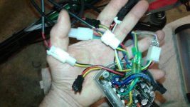
I am trying to connect my Q100H and what I have done so far doesn't power the motor or the LCD display. This is the link to BMSBattery.com's picture of the wiring- bmsbattery.com/ebike-kit/546-s06s-250w-torque-simulation-sine-wave-controller-ebike-kit.html (Sorry, I can't figure out how to include the BMS Battery web picture in this post). The attachment tries to display the wires in the same order that the picture from the BMS website has them.

My questions-
1) There is no wire from bike for the "HWBS" connector.
2) There are no "Battery" wires coming form the sine wave controller but I think that is because this is a bottle battery so the bottle battery holder makes that connection.
3) The "Hall Sensor" only has 5 wires going to the connector but the grouping of wires from bike numbers 6. There is no slot in the connector to for the white wire.
4) There is no wire from bike for the unnamed black wire below the "Speed Sensor" connector.

Thank you for any help you can provide.
View attachment 1
 

Attachments

  • 20170621_073914_resized.jpg
    20170621_073914_resized.jpg
    43 KB · Views: 1,502
The missing wire in the Hall connector from your controller is for the speed sensor in the motor. Did BMS Battery give you an external speed sensor to mount on the motor? If so, you can attach that to the corresponding connector on the controller. Then you can ignore the mismatch between 6 wires coming from the motor and 5 wires from the controller.

If you didn't get an external speed sensor, then either buy one, or use the built in sensor in the motor., This requires you to bring the white wire from the controller speed sensor connector to the Hall connector, if it has an empty terminal. The other two wires on the controller's speed sensor plug are for power and ground, which are already there in the Hall connector.

Controllers usually don't work right without a speed sensor. Odometer doesn't work when coasting.

Is the un-named black wire designed to plug to itself? Probably a speed limiter.

The LCD should power up without motor, throttle, or PAS connected, but it might toss an error code.
 
You have to connect the battery. If you look in the comparment on the base where the controller goes, there are two wires connected to the pins. The controller has to be connected to them.

Your controller has two matching wires (bottom right of your 2nd photo). Did you cut them to remove the controller?

The white wire from your motor connector needs to go to the signal wire on the controllers speed sensor connector.
 
If you want to use a HWBS, the colours on the sensor are unusual. red is 5v, yellow is ground and blue is the signal. On the controller brake switch connector, black is ground and yellow is the signal, so you connect blue to yellow, yellow to black and then splice the red into any other 5v, like the throttle red or the PAS red.

One other point. If your motor runs rough at certain speeds, you'll have to pl;ay with the P1 parameter setting in the LCD.

The blue and black wires with the small black connector are for cruise control. You put a momentary switch on it to engage/disengage cruise. Alternatively, you can get automatic cruise control by bridging those two wires, where the cruise comes on after 5 secs of constant throttle and is disengaged by a brake or by blipping the throttle. I don't recommend that because the cruise always engages when you don't expect, which leaves you with full power when you throttle back sometimes.
 
The identified plugs from the picture off of BMSBattery.com in an arc from left to right HWBS (black and not connected to anything), Brake (white), Throttle (white), Hall Sensor (white and my finger is on it), PAS (Black and above my finger to the right), Speed Sensor (white and on top of a black wire in the picture), unkown (black and not connected to anything), and Meter (white).
 
docw009 said:
The missing wire in the Hall connector from your controller is for the speed sensor in the motor. Did BMS Battery give you an external speed sensor to mount on the motor?

Is the un-named black wire designed to plug to itself? Probably a speed limiter..

Thanks for solving the mystery of the white wire. Yes, they did give me an external speed sensor and it is connected to the small white plug, 6th from the left.

The un-named plug (7th from left) is a female two wire and can't plug into the into the 1st plug which BMS Battery calls the HWBS as it is a male three wire.
 
You don't need the external speed sensor because your motor has an internal one. You just connect the white wires.
 
d8veh said:
You have to connect the battery. If you look in the comparment on the base where the controller goes, there are two wires connected to the pins. The controller has to be connected to them.

Your controller has two matching wires (bottom right of your 2nd photo). Did you cut them to remove the controller?

The white wire from your motor connector needs to go to the signal wire on the controllers speed sensor connector.

The 2 wires at the bottom right of the 2nd photo are connected to the holder for the bottle battery. I didn't show it in the picture.
 
d8veh said:
You don't need the external speed sensor because your motor has an internal one. You just connect the white wires.

Is it wrong to use the supplied external speed sensor?

If you are suggesting I discard the sensor I hooked up, I don't understand where I would marry the white wire from the Hall Sensor array of wires from the motor to the controller board. Should I cut the Speed Sensor (6th connector from left) and twist the white wires together? Wouldn't it be easier to use the supplied external speed sensor?
 
So I am going back and forth from the help you all are providing back to the bike in the garage. I feel I am gaining in understanding.

I have checked a few things, and I changed:

1) The Hall Sensor wiring. Before, I just plugged the individual wires into the female Hall sensor plug. Then I noticed that BMSBattery supplied me with an empty holder for the array of wires that go into the Hall sensor. I clicked the 6 wires into the holder and then plugged them back into the female Hall sensor. My thought was that the back of the 6 wires may have been making contact with each other. I don't know why they wouldn't have done that at the factory unless they were giving options because the space is limited in the controller compartment.
2) I turned the locking key so the bottle battery was locked in.

When I press the info key, I now have the LCD back light flash momentarily and then the LCD letters stay (very faint) but the back light disappears. I can scroll through the pedal assist numbers (1-5) but when I turn the crank the motor doesn't engage.

I think I am getting closer but I am stymied again.
 
they probably don't do it at the factory because sometimes the wires are in different order.

I would make sure all of your connectors are matching up wire color on both sides. Took me a while to figure out that the colors didn't match on my throttle on my first build, and of course it didn't work that way...
 
RVan said:
When I press the info key, I now have the LCD back light flash momentarily and then the LCD letters stay (very faint) but the back light disappears. I can scroll through the pedal assist numbers (1-5) but when I turn the crank the motor doesn't engage.

Is your battery charged? What is the output voltage?
 
You shouldn't have put the white wire into the 6-way connector because it needs to be connected to the white wire in connector where you connected your speed sensor. how you join them is up to you, but soldering and heatshrink is what I'd do.

You may have put the PAS magnet disc the wrong way round. You can't go by the arrow because they don't know which side you're going to fit it and the arrow would have to point the other way if you changed sides. See if it works when you pedal backwards. Be careful with that.
 
The battery is charged. I brought it to a local bike shop today and of course it seemed to be working??? Embarrassing. It seems the screen has a back light and then goes to LCD only on purpose. There is an override by pressing and holding the top of 3 button pad that controls the on off and level of pedal assit. Don't know why the thumb lever didn't activate the motor when it was upside down but that isn't an issue anymore. I haven't gotten it buttoned up and all the loose wires tucked away so I haven't had a chance to give it a test ride. I will post again when I can steal time away from obligations to see if it is 100% functional.

Thanks again for all the advice.
 
When you switch on the controller, it won't give power until it sees a zero throttle reading, which it would normally get, but if your bike was upside down, the lever could be moved off it's stop so not zero throttle.
 
Back
Top