DIY MOT-based Resistance Soldering Unit (RSU)

spinningmagnets

Moderator
Staff member
Joined
Dec 21, 2007
Messages
12,953
Location
Ft Riley, NE Kansas
This thread is about how to cheaply and easily build a MOT-based RSU for your shop (requires 120VAC input), and also a timer for it, along with a way to adjust the amps.

Here is the best tutorial on MOT function and design theory.
https://www.ibiblio.org/kuphaldt/electricCircuits/AC/AC_9.html

Just about everyone here is already familiar with soldering, You buy a 100W soldering iron and when you plug it in, the tip gets hot. You dab some solder onto the tip to help transfer heat to the connectors/wires/etc...and then, when everything that you need to have bonded has heated up enough, you feed a very thin wire of solder onto the hot joint.

"Resistance Soldering" (RS) means you pass electricity through a piece with two probes (or, you clamp a probe onto a part near the joint, and touch the place you want to get hot with one probe). The voltage is not very relevant, although it is better for it to be low. It is the amps we want, to heat the part. An ES member has achieved good results (attaching thick bus-strips to an 18650 cell-end) with a professional $450 unit from "American Beauty", and although it is adjustable for current, his good results were achieved at 3V and 40A = 120W. If the RSU provides as low as 3V, or as high as 48V, the amps are what will heat up the part (edit: I now believe the volts do have some effect, not fully understood yet for RS).

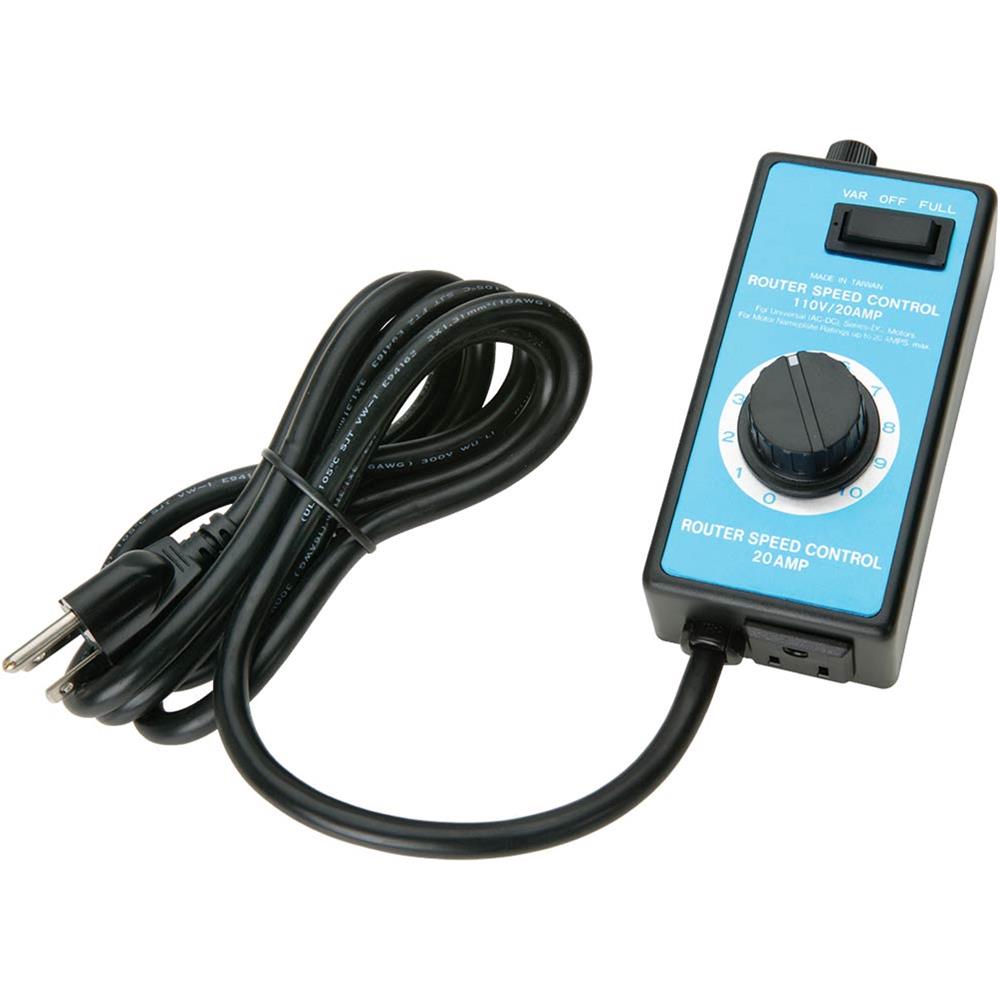
Low volts puts less strain on your home's 120V AC breakers (voltages above 60V are very dangerous because they can penetrate dry human skin, lower is safer). One of the DIY RSU's I found uses a high-amp 6V battery charger that is adjusted with an inductive-style dimmer switch.

For instance, the average USA home's circuits might be 15A X 120V AC = 1800W. Since we are starting up a sudden high-amp load, we should not go over about 1500W to prevent the breaker from tripping (sudden surge). Then, since we are converting the type of electricity through a cheap and inefficient transformer, we should knock off about 10% for conversion losses, so...now we are down to working with 1500W X 0.90 = 1350W. This means if we convert the household current to 48V, then the most amps our DIY kit will put out is 1350W / 48V = 28A, and we want at least 40A (with the option to go a little higher). By going right to the lowest viable voltage (approx 3V), we can have as much as 1350W / 3V = 450A...way more than we will ever need. 1350W / 12V = 112A, so...12V is the highest voltage I'd recommend for cost of parts and convenience.

Below is a pic of a transformer tucked inside a microwave oven (discharge all capacitors and wear rubber gloves when pulling these out, there can be a nasty high-voltage spark)

cimg1940-microwave-oven-interior.jpg


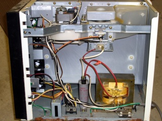
If you have only one type of RS job to do over and over, you can rig-up a Microwave Oven Transformer (MOT) as a simple, crude, and cheap current supply. You can keep swapping-out different wire diameters on the secondary coil until you get the amps that work for the job. That being said, I believe there is a great value in having some small amount of adjustability in the current.

file.php


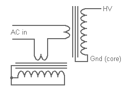
In the pic above, a builder has acquired a transformer from a used microwave oven. He removed the secondary coil (made from many wraps of very fine wire), and then replaced it with 1-1/2 wraps of very thick wire (welding cable). The alternating AC current in the primary coil creates a pulsing magnetic field. That pulsing magnetic field (60-Hz means it reverses its direction 60 times a second), causes the secondary coil of fat wire to generate a low voltage and very high amps (with roughly a 10% loss of total watts due to the inefficiency of this method).

The MOT-based spot-welders require a large MOT, or at the very least, two smaller MOTs in parallel. The smaller microwave ovens are much more common, so an RSU made from a small MOT should be very cheap and easy to put together.

Spot-welders must partially melt the nickel bus-ribbons at above 2700F / 1450C (in one tiny spot), so the pulse must be extremely short in order to prevent heat damage to the cell (less than 200 milliseconds / 200 ms), or 2/10ths of a second. The RSU only needs to heat the solder paste to about 450F (232C) for around 2 seconds. It has been successfully done "by eye" with no timer, but a very simple and cheap timer should be possible for us to identify or build.

Here's a 15-min video of cutting open an 18650 after its been soldered at both ends to see if there is any visual damage (cutting starts at 6:22, comparison at 7:44). The conclusion at 8:40 is that conventional contact soldering might be damaging to the negative, but the positive cathode nipple is far enough away from the active battery material that it was not damaged. The cathode would be even more safe if you were resistance-soldering a tab for 2 seconds (much shorter than the technique shown in the video below, at the 2:00 mark), or...conventionally-soldering a fuse-wire to the cathode.https://www.youtube.com/watch?v=YrqsAGr41uU

Here are websites with info on doing this
http://technitoys.com/diy-resistance-soldering-outfit/

Here's is a very good article on harvesting a MOT out of a free trashed Microwave oven, with pics.
https://softsolder.com/2010/09/08/resistance-soldering-transformer/
https://www.youtube.com/watch?v=-NLy-LL_TGQ&t=374s

There are 100 youtube videos about making a MOT welder, but I consider this video very good. He considers it a failure because he wanted to weld aluminum, but...his resulting amps and volts are exactly what we want.
https://www.youtube.com/watch?v=fQXBNkaB1tU
https://www.youtube.com/watch?v=I3fQjlInC44

great video explaining the physics of MOTs in plain english for newbies
https://www.youtube.com/watch?v=jDuxFEgtSAQ

This guy shows how to connect two MOTs in series to increase amp. he uses two large MOTs to make a welder, but this could be useful for us to use two small MOTs, if big ones become unavailable.
https://youtu.be/hsfgwEUXtTc

If you don't need maximum copper cross-section, but your secondary is getting hot from a frequent duty-cycle, one builder made a secondary out of copper tubing, and flowed coolant through its center. Of course the tubing had heat-shrink over its entire length, and you would need to cut off the "I" section of the core, then re-clamp the E and I back together after inserting the coil.

Just got this, from a 1580W (1.58 kW) large GE built-in microwave.
Aug 2008, Model # HVM1540LN1CS...after the secondary was removed, the "window" space has a cross-section of 15mm X 31mm.

A hobby railroad model enthusiast tutorial
http://www.freerails.com/view_topic.php?id=4345&forum_id=57&page=1

Based on my research, the total power of your MOT RS unit will be the strength of the magnetic field in the transformer "window", times the amount of copper mass passing through that window.

We have all seen higher volts (120V / 240V) passing through much thinner wire without getting that wire hot, so...it is the amps that determine the heat you will get. Once you have wrapped a coil that fills the secondary window, the total output power in watts will be the same regardless of the volts and amps. High turns of thin wire will result in higher volts and lower amps. Fewer turns of thicker wire will be lower volts and higher amps. Since you can adjust the input downwards, and we are only interested in the amps, you should shoot for low volts and high amps. Any volts below 3V may have an inconsistent connection to the work-piece, and any volts above 12V are unhelpful. Any volts above 60V may penetrate dry human skin, so a number or wire wraps equaling 3V-12V is recommended.

Even without adding some type of input adjustment to the power, you can add a tap to the middle of the secondary coil, resulting in three leads exiting the secondary. Since current will only flow through a complete circuit, such a center tap can easily and inexpensively provide three different maximum amp levels, while it also does not limit the original coils' max amps. For instance, imagine we can fit a fat wire into a coil that fill the window by using 6 turns. If we add a center-tap at the 2-turn mark, we immediately allow ourselves to access the sections of the secondary coil at the 2-turn, 4-turn, or the full 6-turns of the coil.

Amps are more complex to accurately measure, but volts are easily tested. Most common MOTs have a primary coil that is wound so that it provides one volt per secondary turn. Our theoretical center-tapped secondary would then provide 2V, 4V, and 6V. If slightly thinner wire is all that is readily available, you can fit more turns into the secondary window. In such a case, consider arranging the center tap to provide 3T, 6T, and 9T, or...4T, 8T, 12T. If you reach 12 turns and there is still significant wasted airspace in the secondary window...consider unwinding it, stripping the insulation from the available wire, and doubling-up its thickness (or even tripling). If you do this, you absolutely must add heat-shrink insulation before re-winding the secondary again.

Once you have tested the resulting MOT/RS unit...and the results are working well, it is advisable to spray or brush some varnish over the secondary coil in order to reduce vibration from the alternating magnetic field, Such vibration will cause chafing and will wear away the insulation, eventually causing a short.
 
What are the benefits of RS, and who would want to use this method?

1) The current (and heat) can be turned on-and-off by a foot-switch. Once the switch is off, the probes will be warm, but nowhere near as hot as a large conventional soldering iron would be (the RS probes will be much cooler than the soldered part).

2) Heat creation at the joint is almost instant, rather than waiting for the iron to heat up between joining operations, and waiting for the joint to get hot enough to melt the solder.

3) With a common conduction "contact" soldering iron, you must pull the iron tip away from the joint to remove the heat, but...that is just the moment when the solder is molten, and has not yet solidified. With an RS unit, once you turn off the power, the joint begins to cool and solidify, but...the probes can be used to maintain pressure on the joint at all times, until it is finally secure.

4) Some tricky soldering jobs seem to need three hands. By clamping a probe near where you want heat, and activating the current by a foot-switch, one hand can be precisely placing the second probe to apply heat in a certain spot, while your other hand is free to be feeding-in solder.

5) You can easily bond thick copper busses to cells. With spot-welding a thicker copper bus to a cell, the required machines are expensive, compared to the common nickel spot-welding machines. If using a common conduction-contact soldering method, a thicker strip of copper bus-ribbon becomes very hard to attach without harming the cell from too much heat. The "heat-sinking" of the thick copper ribbon requires long contact times to get the joint adequately hot enough (which allows heat to penetrate deeply into the cell). With RS, the copper bus barely gets warm due to the low current resistance of thick copper.

The solder is the most resistant part in the electrical-circuit path, so...the heat originates at the solder and radiates outward (if one probe is on the cell-tip, and one probe is on the copper bus). When you stop applying current, the copper bus will then pull heat away from the freshly soldered joint. If you have two copper strips on the cell tip (that are not touching), and pass current from one strip to the other, current will flow through the solder, which I suspect will leave the steel cell-tip even cooler.

If connecting a tiny fuse-wire to the positive cathode tip, this benefit would be even more pronounced.

Why copper busses?

Spot-welding common 0.15mm - 0.20mm thick pure nickel is well-known. Nickel has a conductivity of roughly 25/100 compared to copper. Meaning that a copper bus with the same thickness as a nickel bus can conduct 4 times the current without overheating. Nickel is pricey, and is likely to go up in price very soon. Bus strips must be ordered, and then you wait for it to arrive. Copper is cheap and readily-available in every major city.

However, spot-welding copper is very difficult, as is a thicker nickel bus (0.25mm-0.40mm). If you want a high-amp battery pack, you should investigate copper as a bus material.

As to the connection method, The 18650 cell cans are either stainless steel, or nickel-plated common steel. I believe the "compression" method of pressing the buses against the cell-tips is worth considering. However, there are many who want something more. I now believe that the best method of connecting a copper bus to the broad and flat negative end is using a 12mm X 3mm button magnet, and the positive tip should have a fuse-wire connected to it. Tesla uses ultrasonic vibrations, but for the home-builder, I now feel RS is the best attachment method...whether the positive uses a fuse-wire, or a flat ribbon.

Regardless of what we are soldering, once you try an RSU...I think they will become quite popular.

Who currently uses an RSU?

Plumbers who connect copper pipe.
There are places where it is dangerous (or just difficult) to use a brazing torch, and the RSU can solder a pipe joint in a tight spot while easily reaching temps of over 1200F (if needed).

https://www.youtube.com/watch?v=UYEc8Gfp-js

Scale-model railroad hobbyists.
These people weld tiny brass parts. Torches or large soldering irons can cause warpage, and small irons may not be able to produce enough heat to get the joint hot enough (and faster than the heat is pulled away by the mass of metal)...Heat transference with conventional soldering is dependent on contact, and oddly-shaped parts may have poor soldering-iron tip contact, while the brass also heat-sinks the applied heat away from the intended joint. With an RSU, if you can touch it, it will get hot, and...it will send less heat into the nearby parts compared to a contact-conduction iron.

https://www.youtube.com/watch?v=UYEc8Gfp-js

Electrical component assemblers. There are some tightly-clustered components where a soldering iron would re-melt nearby soldered-joints. Also...even if an RSU probe touches a nearby component, the current will only flow through the completed electrical path between the two probes.

By switching to fatter or skinnier probes (and cables), you can adjust the amps to the size of the soldering job. Attaching large copper lugs to fat copper cables, and also tiny electric components can BOTH be soldered too by the same machine (if the amps are adjustable).
 
AMP-adjusting ideas

xxxxxxxxxxxxxxxxxxxxxxx
Putting a motor speed controller on the input

Fechter has stated that a cheap motor control speed device will likely work much better for adjusting the amps compared to a dimmer switch. Often sold as a router speed control or table-saw speed control for $20-$50 (lower RPMs allow cutting aluminum and plastic). edit: early experiments seem to indicate that these do work for this, but they do not adjust down completely to near zero.

[light] Dimmers typically work by switching the current on and off rapidly (well, chopping bits out of the normal sine wave shape of the AC); this is fine for a resistive load like a bulb filament, but will not play nicely with an inductive load like a transformer

I just built a MOT welder. I use a Lutron ceiling fan speed controller that I bought at Lowes…it is designed for an inductive load…under $10 (this is a quote from a random anonymous poster on the internet, proceed with caution)

Are the dimmers that are discussed here the kind that are designed for transformer (i.e. inductive) loads ?
The standard 'home and garden' type dimmers that are sold over here are designed for incandescent light bulbs, and play havoc when hooked up to a transformer due to the phase angle that the transformer coil puts between the AC voltage and current. A -much more expensive- 'Halogen' type dimmer has additional circuitry to compensate for this, they can handle up about 500 VA. The VA=Volt-Ampere instead of the W=Watt denotes the inductive type of load. I used such a dimmer to control the primary coil of a cheapo MIG welder with a defective wire transporter to give a fully adjustable 0 to 80 Amps DC output.

prod_5697311327


I have seen professional heavy-duty RSU's that have several lugs to choose from when attaching the two probes. They are sometimes labeled with voltages. After some study, we know that on this style...higher volts is also higher amps due to the increased copper mass of the coil selections occupying more of the available magnetic flux.

This is a pic of a DIY hobbyists' RSU, which is a copy of a larger professional unit. How does this work?

RSU1.png

RSU2.png

https://www.eevblog.com/forum/beginners/arc-welder-triac-controler/msg808910/#msg808910

With resistive load (incandescent bulb) every schematic of dimmer works well, even far more simple schematic. But with highly inductive load as a welding transformer, there are a lot of troubles.

If there is any asymmetrical triggering of the triac, the transformer will saturate and a very high current will flow through the primary winding, with magic smoke and / or trip of the circuit breaker. One of the greatest weaknesses of this simple schematic is that the pulses are very short, only 2 or 3µs. With highly inductive load, this it not enough to ensure that current reaches the value of the holding current at the end of the triggering pulse, and the triac can lose the conduction. Even worse, the + and - holding currents are not exactly the same, so triac can trigger during one alternance and not during the other, saturating the transformer.

It would be very important to verify with an oscilloscope if this trigger circuit is really generating a pulse train. But for doing this, you will need a differential probe or to feed the dimmer and load with an isolation transformer. In every case, don't try to dim your welding transformer without a resistive load in parallel with the primary (your incandescent bulb)

I just remembered that in the professional RSU videos, there is a bulb that lights when the power is on...interesting.

xxxxxxxxxxxxxxxxxxxxxxxxxxxxxxxx

Adding several taps off of the secondary coil

Here's 2 minute video about one of these units, and the instructor specifies that the three taps will access different secondary windings. By attaching the two probes in various combinations, you will be provided with three different amp ranges (A+B, A+C, B+C), and then the dial provides some adjustment too, which I suspect may be similar to the "router speed controller" that affects the primary winding, listed above.

https://www.youtube.com/watch?v=z6yL4bGVXyU

[youtube]z6yL4bGVXyU[/youtube]

I watched tons of videos on youtube, I am now certain the "three lug" style (on the output) has only one added tap to achieve three voltage settings. The microwave transformers seem to have a common construction that provides one volt per secondary turn, so this would be 2V, 4V, and 6V...all well within the target of keeping a 40A pulse below 1200W

This is just like parabellum suggested below.

RSU4.png

xxxxxxxxxxxxxxxxxxxxxxxxxxxxxxxx

Here's a schematic of one example of an amp-adjusting method, for anyone who understands these things
http://www.geocities.ws/kammer0072000/features_control_cct.html

xxxxxxxxxxxxxxxxxxxxxxxxxxxxxxxx

Using a second MOT as a variable inductor

http://www.mike-worth.com/2013/07/31/adding-a-current-limiter-to-my-mot-welder/

Without going into too many details, an inductor essentially acts like a resistor to AC currents (although an ideal one doesn’t dissipate any energy as heat); my plan was to put it in series with the primary of one of the transformers to limit the current going in and therefore reduce the current coming out. Using an MOT as an inductor is simple, the only tricky part is making it adjustable. Generally inductors consist of a coil and a core; changing the number of windings on the coil would have been tricky and would probably have resulted in bad connections and ruined insulation, but changing the core was fairly straight forward. The E and I sections placed together form a flux circuit; the aspect that matters here is that changing the cross section of this flux circuit will alter the total inductance.

It is easy to change this cross section by partially sliding the E piece off the top of the I piece; to support the core while this happens, I bent and welded a couple of bits of steel into guards and added some wood to support the E piece

Most common MOTs are "E/I"-core transformers, because of the shape of the lamination stack. In this suggestion, you would un-clamp the I-section, move it over a little, then re-clamp it down. If it remains loose, it will vibrate very badly.

MotorTech7.png

View attachment 2

Here's a link describing how "old style" welding units had a movable section in the main transformer to adjust the amps. looks promising, and easy to do...
http://info.ee.surrey.ac.uk/Workshop/advice/coils/leak/weld/index.html
https://www.hobartwelders.com/weldtalk/archive/index.php/t-39775.html

xxxxxxxxxxxxxxxxxxxxxxxxxxxxx

Adding a variable inductor to one of the secondary cables

http://adammunich.com/microwave-transformers/

Ballasting

MOTs are a mass produced item and these days quantity is more important than quality. Because of this, they are designed with as little iron as possible and drawing an arc often saturates the core. Once a transformer is saturated it starts to draw a lot of extra amps; amps that do not make it to the secondary coil, but instead are wasted as heat. An MOT in saturation is likely to trip your circuit breaker and that’s no fun. To prevent excessive current draw MOTs are usually ballasted, and this can be accomplished a couple different ways.

By far the simplest method is just to use a long wire wrapped around some welding rods. Anything greater than 50 or so turns around 25 or so rods should limit the current enough that the MOT doesn’t trip your circuit breaker, and if you like, it’s possible to use a PVC tube form (coil on the outside, welding rods on the inside) to allow for removal of the welding rods. Less rods = Less inductance = more current.

MOT9.png

An alternate ballasting option is to use another MOT an a series inductor. All you need to do is put the primaries of 2 MOTs in series, then short out the secondary of one MOT (see right). The one with the shorted secondary becomes a high current inductor, perfect for ballasting another MOT. This is the preferred method of current limiting since there isn’t much that can go wrong and not too much power is lost as heat. It certainly adds a lot of weight though…

ballast.PNG


A video on using a second MOT as a variable inductor
https://www.youtube.com/watch?v=RsfEsef3JeQ

xxxxxxxxxxxxxxxxxxxxxxxxxxxxx

Adding and removing several light bulbs in parallel to limit current

edit: this looks like a dead end, after some study

You may recall from our bug zapping light saber build that these devices work by providing two energized grids. When an insect flies between the grids it allows the potential energy to overcome the air resistance by travelling through the insect’s body. The Megazap uses a transformer from a microwave oven to source that potential. The transformer produces 2.4 kV and the current is limited by a floodlight fitted inside the microwave. The side effect of using the lamp as a limiter is that it lights up with each bug zapped, providing a bit of a light show

If we can limit current by adding a light in-line with one of the probe cables, can we have several small lights in parallel to add one-by-one to vary the resistance? Is it better for the resistance-lights to be on the primary coil or the secondary?

http://adammunich.com/microwave-transformers/

A third method of ballasting MOTs is to use a resistive ballast. Halogen lamps (the big 500W work lamp kind) make pretty good resistive ballasts. All you need to do is put one in series with the transformer’s primary to limit its ability to draw current. Make sure you find a non-combustible way to mount them since those things get hot! Also, since they are glass don’t touch them you as your finger oils will burn when the lamp is powered up and the resulting carbon will get hot enough to shatter the bulb

xxxxxxxxxxxxxxxxxxxxxxxxxxx
Custom-winding an E/I transformer
An interesting patent. If you place one magnet near another magnet, and they are unable to move freely, plus they are positioned to have opposite poles facing each other...the magnetic forces will somewhat cancel each other out. This is how a "magbase" turns on and off. This p[atent shows a relatively conventional E/I transformer, but it has various arrangements of electromagnets wrapped around certain parts of the lamination stack. By adjusting the power flowing through these auxiliary electromagnets, the magnetic path of the primary and secondary coils is disrupted, and the amount of coupling magnetic force between them becomes adjustable by adjusting the power going to those extra electromagnets.

http://www.google.com/patents/US4206434

xxxxxxxxxxxxxxxxxxxxxxxxxx

Using an external variable electromagnet to shunt the mag circuit of the MOT to reduce the output in an adjustable way.
http://sparkbangbuzz.com/mag-amp/mag-amp.htm

xxxxxxxxxxxxxxxxxxxxxxxxxx

Using multiple secondary coils in parallel to vary amps.
http://www.electronics-tutorials.ws/transformer/multiple-winding-transformers.html

xxxxxxxxxxxxxxxxxxxxxxxxxx

old welders moved a shunt in or out of the flux to couple or partially de-couple the primary and secondary coils, in order to vary the amps. Some even moved one of the coils closer or farther away from the other coil. In the video below, FF to 5:15. (this instructional video also mentions that the length of the cables can affect the output at the welding point.

https://youtu.be/CW7I-ymfINU?t=316

from a DIY MOT-welder discussion:
the small shunts in the transformer cores are to limit the short circuit current and peak power the transformer has to carry

From MOT patent #US4812798

A second problem related to known transformer structures or microwave ovens is the fact that the magnetic shunts, positioned between the primary coil and the secondary coil fulfilling the function of current limiter required for a leak transformer, very often have a poorly defined position, and their electric insulation is difficult to provide.
Another aim of the present invention is then to provide means for positioning the magnetic shunts accurately while repetitively providing an air gap whose dimension is well defined, so as to ensure the repetivity of calibration of the transformer for mass production. The magnetic shunts are positioned by means of the carcasses and covers which simultaneously provide 10 kV dielectric insulation between the windings and the electric shunts as well as the leak line distances required by the safety standards of different countries, by positioning on the central leg of the magnetic circuit and so not haphazardly.
The structure of the invention makes it possible to assemble and fit the shunts and coils in the magnetic circuit automatically or semi automatically.
The shunts are grounded by contact on the internal part of the external leg of the magnetic circuit, or by an electric ground connection with the shunts and the magnetic circuit. In all cases, the metal plates forming the shunts are immobilized in all directions, so that they cannot vibrate and cause noise.
Once impregnated with varnish, the mass formed by the varnish, the covers and the shunts substantially lowers the sound level of the transformer, which is an additional safety measure for mass production.
 
Timers

ridethelightning recommended an adjustable 555-based timer connected to actuate a solid-state relay, both readily available and cheap (both less than $10 each)

images


images
 
Solder Paste

EDIT: I don't like lead-free solder, avoid it if you can. My favorite is 63/37% Tin/Lead (and even 60/40 is good)

There may be a better deal out there somewhere, but I found a small jar of SAC305 solder paste that was 50 grams for $17 at sparkfun (part # TOL-12878). If you want to experiment first, you can buy smaller amounts in hobby syringes on ebay.

https://www.sparkfun.com/products/12878

I recently found out about solder paste. It is a paste made from microscopic balls of solder that is mixed into a thick gel of flux, and mixed in the perfect ratio between solder and flux in order to consistently provide good results.

There are several ways in which using solder paste can make certain soldering jobs easier. By applying the right amount of paste, and putting it right where you want it. you can then clamp the two parts together and then take your time using your two hands to manipulate the two RS probes. Apply a second or two of current with the foot-switch, and the job is done.

The most common industrial "lead-free" solder is SAC305, which stands for Sn / Ag / Cu (Tin, Silver, Copper), and the 305 refers to the silver being 3% and the copper being 0.5%, the remaining 96% is Tin.

If you already have a very secure electrical connection between two pieces, and you only want the solder to hermetically seal the joint away from oxygen and humidity, you might consider a solder alloy that is roughly half Tin (Sn) and half Bismuth (Bi) which melts very easily at the lowest possible soldering temps. These solders have a worse electrical conductivity than the steel cans on 18650 cells, and SAC305's conductivity is 13/100 IACS, which is a hair better than steel, so as long as the SAC305 solder is thin, it does not present a bottle-neck to the existing cell materials' current flow.
 
Magnetic Shunts
(keep them or throw them away?)

Finally found a technical page describing the type of magnetic shunts shown in the MOT teardown videos, and how they work, and why they are used.
http://www.vias.org/eltransformers/lee_electronic_transformers_08_06.html
Filaments of large vacuum tubes sometimes must be protected against the high initial current they draw at rated filament voltage. This is done by reducing the starting voltage automatically through the use of a current-limiting transformer, with magnetic shunts between primary and secondary windings. The shunts carry very little flux at no load; as the load increases, the secondary ampere-turns force more of the flux into the shunts until at current Isc, Fig. 194 (B), the output voltage is zero.


All the MOTs I've worked with have magnetic shunts in them. They look like a flat stack of lamination pieces about 1/4" to 3/8" thick, inserted in the winding space between the primary and secondary windings. The most desirable transformers come from the earliest Litton or Amana RadaRange ovens. Those monsters were rated for something like 1500 watts nominal, much better than the wimpy little 900 watt units in the current production Sanyo or Samsung ovens. Commercial MWOs also have very overrated transformers, as they are expected to be in pretty much continuous operation. The transformers in domestic MWOs run very hot, and are minimally rated, with the assumption of a very low duty cycle. In normal operation, the magnetron tube behaves like a 4 kV Zener diode. The magnetic shunts limit the transformer output current to prevent the runaway consumption of current during oven operation.

The shunting function of a MOT shunt in not as dramatic as that of a NST (Neon Sign Transformer). While you can theoretically run a NST indefinitely with the secondary shorted, OTOH, even with the shunts in place, a shorted MOT will still draw enough power to burn up, hence the need for external ballasting of MOT stacks. In my experience, most Tesla Coil builders drive out the shunts to get a bit more power output from their transformer stacks. Oil immersion is a big help in improving the power handing capabilities of series MOT stacks. Better stock up on MOTs while you can get them. The newest ovens use a solid state high frequency oscillator, like a TV flyback transformer on steroids, instead of the heavy iron transformers of the original ovens.

https://www.eevblog.com/forum/beginners/arc-stabilizing-in-a-ac-welder/
To reduce current, you must increase the short circuit voltage using magnetic shunts. (see picture)

http://www.qsl.net/kh6grt/page4/xfmr/pictures/transshunts.jpg

With a 2.5mm dia welding rod, welding current should be chosen between 50A and 100A
 
Here's a crappy drawing I made to help me ask a question. We know that 1.5 wraps of fat wire around the secondary of a common MOT results in roughly 3 volts, which is beneficial for several reasons. In order to vary the amps, can we separate the many strands in that fat cable that makes the secondary coil, re-group them into three smaller bundles, and then by choosing one bundle, two, or all three...will the result be three different levels of output amps? (since electricity will only flow through a complete circuit?)

RSU3.png

file.php
 
spinningmagnets said:
Here's a crappy drawing I made to help me ask a question. We know that 1.5 wraps of fat wire around the secondary of a common MOT results in roughly 3 volts, which is beneficial for several reasons. In order to vary the amps, can we separate the many strands in that fat cable that makes the secondary coil, re-group them into three smaller bundles, and then by choosing one bundle, two, or all three...will the result be three different levels of output amps? (since electricity will only flow through a complete circuit?)
I would take series approach, with exit on every wrap. This way you get 1V,2V,3V or Low,Mid,High. Where higher Voltage has the potential to push more Amps if conductor is fat enough.
Like this:
 
Used MOT's are cheap and available, also, since we don't need a rare 1500W unit to make a spot-welder (which uses a shorter pulse than RS, but higher amps), the more common 800W microwave ovens are practically free. Our target is 40A, at voltage anywhere from 3V to 12V, and any adjustability in the amps would be appreciated, but not vital.

I have already purchased the cheap and small inverter-type welder to use on its lowest setting, and I will definitely report on that. I have the router speed controller to test a MOT as an RS unit (fingers crossed).

And now!...a third contender has stepped into the ring. I stumbled across a video that inspired me, it is a portable 18650 DIY soldering iron. A conventional conduction-contact iron, using 1S / 4P of high-amp cells. 4V, and four 10A-rated cells together making 40A. That sounded familiar to me. A 2-second burst of amps is just what an 18650 vaporiser uses.

The on/off switch is near the tip, and it actuates a FET on the battery case to start and stop the current, so...I guess the single-cable has two fat wires for current, and two skinny wires for on/off? The question now becomes, how do we limit and adjust the amps in a dead short, if we use "X" number of high-amp 18650 cells?

https://www.youtube.com/watch?v=eYBXO418irc

ResistanceSoldering1.png

Edit, I have started a new thread on making and using a portable RSU that uses 18650's

https://endless-sphere.com/forums/viewtopic.php?f=2&t=89379
 
You get those guys everywhere. I purchased my from HK and used 2 Nickel–zinc batteries, iron was fast, but lasted few month at moderate use. Many regulated iron station use this principle. It is cool, but other topic.
I think, any 200W transformer easily can make RSU (you need to run current trough work peace even if it does not make most of resistance path) , look at videos of this post https://endless-sphere.com/forums/viewtopic.php?f=14&t=88965&start=50#p1302533 .I Intend to cross post all relevant info here, and use mentioned tread for all discussions and polemics.
What do you think?
 
Here is the 18-second video (from ES member overclocker) that convinced me to research this:
https://www.youtube.com/watch?v=6V-XCkeC8Xk
"This video has been removed by the user." :(

El Cheapo Resistance Soldering Unit
https://www.youtube.com/watch?v=Uwl3Ezm6nQc
NOTICE what he is using for a resistance soldering unit :)
That is at 1:56 in the video

While reading some model railroad forums I found a reference to power levels:
Low Power units: 250 watts (example: HOTIP model H-101A)
High Power units: 500 watts
A Weller D550 soldering gun is rated at 240/325 watts ........ h'mmmmm :?: :idea:

I note that American Beauty has units up to 3000 watts (not cheap)
 
Thanks parabellum and LewTwo. I appreciate the help. I just found this when researching magnetic shunts:

All the MOTs I've worked with have magnetic shunts in them. They look like a flat stack of lamination pieces about 1/4" to 3/8" thick, inserted in the winding space between the primary and secondary windings. The most desirable transformers come from the earliest Litton or Amana RadaRange ovens. Those monsters were rated for something like 1500 watts nominal, much better than the wimpy little 900 watt units in the current production Sanyo or Samsung ovens. Commercial MWOs also have very overrated transformers, as they are expected to be in pretty much continuous operation. The transformers in domestic MWOs run very hot, and are minimally rated, with the assumption of a very low duty cycle. In normal operation, the magnetron tube behaves like a 4 kV Zener diode. The magnetic shunts limit the transformer output current to prevent the runaway consumption of current during oven operation.

The shunting function of a MOT shunt in not as dramatic as that of a NST. While you can theoretically run a NST indefinitely with the secondary shorted, OTOH, even with the shunts in place, a shorted MOT will still draw enough power to burn up, hence the need for external ballasting of MOT stacks. In my experience, most Tesla Coil builders drive out the shunts to get a bit more power output from their transformer stacks. Oil immersion is a big help in improving the power handing capabilities of series MOT stacks. Better stock up on MOTs while you can get them. The newest ovens use a solid state high frequency oscillator, like a TV flyback transformer on steroids, instead of the heavy iron transformers of the original ovens.

Can we leave a space between the two coils and then slide various shunts in and out to vary the amps?
 
Yet another concept .....

We all have these 36 or 48 volt battery packs. It might be convenient to be able to use them as the power source for soldering particularly if you happen to be working on your e-bike's cabling. From what I have been able to find in various DIY Resistance projects it is the Wattage that counts and that can be anywhere from 50 to 250 watts for the size stuff we are looking at. So could it be as simple as using a Constant Current/Constant Voltage power supply and a carbon probe?

What I am thinkingg about here is a DP50V5A "Numerical Control DC Step Down Power Supply". You can find these on Amazon, Ebay or Banggood for about $35.

DP50V5A(600).jpg
Short Specs:
Features:
Input voltage: 6-55V
Output voltage: 0V-50.00V
Output current: 0-5.000A
Output power: 0-250W
Youtube: https://www.youtube.com/watch?v=W5gjrq_9t_s&t=204s
Manual: View attachment DP50V5A-Manual.pdf

The advantages are:
1) it will work with most of our battery packs
2) current and voltage limit control
3) relatively cheap (compared to a commercial RSU unit)
4) very compact

Disadvantage:
At only 5 amps one is looking at having to use DC voltages of 20 to 50 volts to reach 100 to 250 watts but is that really a problem?
This is far too simple. Somebody please to tell me what I am missing :roll:

Edit:
As an alternative there is a 15 Amp model that has an input range of 6.00-60.00V. It is two pieces and somewhat larger.
s-l225.jpg


PS:
They also make a nice little case for it: http://www.ebay.com/itm/272726422302
 
I would like to suggest that the watts of a unit are only relevant for RS on the input side, since we are wanting to be able to use a 120VAC /15A = 1800W outlet that is common in houses and apartments. We want to end up with 40A (plus or minus) regardless of the volts. By shooting for a low 3V, we have access to a range of 10A up to as much as 400A. Even at an output as high as 12V, we can still access to a max 100A (assuming a 30% conversion loss due to using an inefficient and simple transformer).

The American Beauty professional RS units use AC on the outlet side, but I think that is simply because that avoids the need to add any diodes (as an additional cost, plus an additional failure mode component).
 
Well I disagree but it is not my area expertise so I am going to pass on the subject for the moment.

Before anyone tries any of this they are going to have to come up with a set of probes/tweezers/electrodes. I was looking at American Beauty's web site as well. I note that their medium duty tweezers use 5/64 (0.078) inch Stainless Steel electrodes. That is almost exactly 2mm. Now I wonder where one could come up with some 2mm diameter stainless steel rod :D ????spoke.jpg
 
Lew, I apologize if I sounded dismissive. I absolutely have no experience with RS (but give me a week to catch up). I would be very pleased if that $35 power supply worked for connecting 0.30mm thick copper bus strips to 18650 cells in under two seconds.

The stainless steel spoke as a probe-tip is a brilliant find, and right under my nose already...
 
LewTwo said:
Well I disagree but it is not my area expertise so I am going to pass on the subject for the moment.

Before anyone tries any of this they are going to have to come up with a set of probes/tweezers/electrodes. I was looking at American Beauty's web site as well. I note that their medium duty tweezers use 5/64 (0.078) inch Stainless Steel electrodes. That is almost exactly 2mm. Now I wonder where one could come up with some 2mm diameter stainless steel rod :D ????
Do not loose much time on probes, take any roundish peace of SS, like bolt or something else, span to a drill and sand down the point to needed diameter. I took 2 pins of old SS hinges. Life is short :D
 
spinningmagnets said:
Lew, I apologize if I sounded dismissive. I absolutely have no experience with RS (but give me a week to catch up). I would be very pleased if that $35 power supply worked for connecting 0.30mm thick copper bus strips to 18650 cells in under two seconds.
No sweat ... the problem with the power supply is with higher voltages you get arcing and sparking :oops: It also has short circuit detection built in to "protect" it :( The 15 amp PS might work at lower voltages but .... still reading ....

spinningmagnets said:
The stainless steel spoke as a probe-tip is a brilliant find, and right under my nose already...
Thought those might be rather common among this group. The advantage of stainless is that solder will not stick to it. Most of my old spokes are plain steel but I am sure I have a few stainless ones around as well.

At this point I am wondering just how big/heavy the lead wires need to be. Would 10 or 12 Ga be heavy enough ?

I was also thinking of a 5 Volt DC circuit on the tweezers to with a switch and LED linked to a MOSFET to cut power on and off.
 
The short-pulse 40A current is similar to what big hubmotors use between the motor and controller, so having 10-ga wire should be enough, since the RS jobs would have more "off time" than a hubmotor. I guess we'll find out soon enough...
 
spinningmagnets said:
The short-pulse 40A current is similar to what big hubmotors use between the motor and controller, so having 10-ga wire should be enough, since the RS jobs would have more "off time" than a hubmotor. I guess we'll find out soon enough...
I used some junk audio 8AWG cable at ~ 70A, had a suspicion that it is copper clad but it is to heavy for aluminium and to lightweight for copper, 10AWG real copper is enough for sure.
 
Found some good info on MOTs, they are more sophisticated than I thought. Still true that they are made to be as cheap as possible, while leaving a lot of efficiency on the table.

https://electronics.stackexchange.com/questions/38329/transformer-heating-up-without-load

This is a non-ideal transformer whose purpose is to generate typically 1 kW of pulsed 5 kV DC into a magnetron, by driving a half-wave doubler. The turns ratio is designed to give about 2 kV AC to the main secondary winding, one end of which is bonded to the grounded core. An additional secondary provides an isolated supply of typically 3 V at 15 A for the magnetron heater.

As it is intended to drive a capacitive load, the leakage inductance of the transformer is deliberately increased by adding a small magnetic shunt between the primary and secondary coils. The inductance is roughly equal and opposite to the doubler capacitance, and so reduces the output impedance of the doubler. This specified leakage inductance classifies the transformer as non-ideal. The transformer is designed to be as cheap to manufacture as possible, with no regard for efficiency. ... Thus the iron area is minimized which results in the core being taken well into saturation with result high core losses.

The copper area is also minimized, resulting in high copper losses.
The heat that these generate is handled by forced air cooling, usually by the same fan that is required to cool the magnetron. The core saturation is not part of the non-ideal classification, it is merely as a result of the economics of manufacture

I am looking for online answers for the same question. Because an MOT is built as cheaply as possible and forced air cooled, it may mean that all overheat if you just disassemble them, take out the secondary, then hook it up to a wall socket. You have to find a way to "push it to its design limits as a cost saving measure" less.

One way is a variac, which drops wall socket voltage from 120VAC to 80VAC or 60. But unless they are built for a high power, they may overheat too, moreover some modern electronic variacs may output a lot of high frequency harmonics which also cause overheating.

My first idea was just using a capacitor in series to limit the current, and roughly 300uF/160V motor start capacitors give you an 8 ohm reactance at 60Hz that would draw ~15A/120V from a wall socket, the max allowed by UL. But I don't have one handy, and the capacitor that comes inside the microwave is like 0.8uF.

So then I thought all you really need is extra reactance. One idea that naturally comes to mind like a lot of online responders answer is to wind more primary turns but that gives you oversaturation issues as mentioned above (because they are saving on iron too).

Note: at saturation the change in magnetic flux with increased current is zero, and there is no "reactance" generating opposing voltage past the saturation limit, the only thing holding back current flow is the resistivity of the copper in the primary winding, say you hit saturation at 110V by adding too many primary turns, then the leftover 10V to a 120V will generate current as if you applied DC 10V to the bare primary copper, which could be in the tens of amps, depending on the primary DC resistance.

So the best idea I'm coming up with as I write this, is to use inductance, but one separate from the iron core of the microwave transformer. So you basically just get a high power rated coil (maybe a motor or another transformer) which would act like a variac, and power your transformer at say 60V/60Hz, or 80V/60Hz. Also using a 2nd inductor in series is much better than a capacitor which risks creating a 60Hz resonant tank circuit with enormous currents, if you happen on the wrong L and C values, and there is no such risk with an inductor.

Obviously you could drop the voltage with an external nichrome wire from a hair dryer, but resistance wastes power, while reactance limits ac current flow without consuming power (other than having power factor issues, and large back and forth copper current due to poor power factor, for which the power company may or may not charge you for (industrial customers often pay a penalty for poor power factor, and they apply power factor correcting capacitor banks, or pfc motor/generators driven at the right speed and slip to make their inductance look like capacitance).

A flow of current +90 or -90 degrees out of phase with the voltage (capacitive or inductive load) consumes no power I.V.cos(phi), the generator motor at the power station would feel no extra load, if you had superconductors bring you the power from the power plant, and not aluminum and copper.)

But yeah, build your own custom "variac" power limiter with a single setting, usually this means find a suitable inductor such as a motor or transformer, and your whole rig would look like a step-down buck autotransformer. Now I gotta go hunt for such a thing too.

PS. I just measured the primary DC resistance on mine, and it was less than 0.4 ohms, which is below my meters accurate range, but yeah, it's down there, if you drive the core past saturation, it will gush a lot of current through the almost zero DC resistance copper.

10V DC through 0.4 ohms is 25 amps for the portion of the AC cycle past saturation (rms 110V to 120V, btw, actual voltage (sqrt2)/2=0.707 factor greater, 155V peak to 169V actual, meaning a single diode rectified capacitor will charge to the 169 DC peak voltage on a 120V AC rms (root mean square) power socket, not 120V, lot of people don't realize that and try to use a 150V DC rated one on 120VAC, in case you try to use capacitors), and may trip your 20A circuit breakers or fast-blow fuses in the basement, depending on how fast they react.

So it's best not to wind more primary turns onto the same core, but limit the power input externally. (PWM motor speed controls might be another way, if you have a 120V PWM unit, other than harmonics heating issues, if they are issues, I haven't read up on that

Here is a one-page explanation of how a MOT works, written for appliance repair technicians.
http://www.microtechfactoryservice.com/doubler.html

The large transformers that step-down high voltage from overhead power lines to 120VAC are sitting in an oil-bath to help absorb and shed the heat they generate. Inside the housing they don't want a huge amount of space between the transformer and the walls so they add magnetic shunts to the insides of the walls. This way you can stand next to a powerful transformer and you will not feel any magnetism, plus...the housing can then be tightly fitted, so it can be as small as possible.

Advantages of Edgewise shunt compare to width wise shunt
•There are basically 2 types of magnetic shunts. Widthwise and Edgewise.
•In widthwise shunt silicon steel sheets/strips are parallel to tank wall & transformer winding where as in edgewise shunts it is perpendicular to tank wall & winding.
•An edgewise shunt is better than a widthwise shunt because the flux is incident on the thickness (edge) of laminations resulting in negligible eddy loss in them. In an edgewise shunt the effective permeability of lamination as seen by the incident flux is much higher as compared to the widthwise shunt.
•In edgewise shunt flux dose not encounter any non magnetic gaps once it enters the shunt.
•Uniform distance with tank wall can be maintained in case of edgewise tank shunts.

Finally found a technical page describing the type of magnetic shunts shown in the MOT teardown videos, and how they work, and why they are used.
http://www.vias.org/eltransformers/lee_electronic_transformers_08_06.html
Filaments of large vacuum tubes sometimes must be protected against the high initial current they draw at rated filament voltage. This is done by reducing the starting voltage automatically through the use of a current-limiting transformer, with magnetic shunts between primary and secondary windings. The shunts carry very little flux at no load; as the load increases, the secondary ampere-turns force more of the flux into the shunts until at current Isc, Fig. 194 (B), the output voltage is zero.

also http://www.freepatentsonline.com/3622868.html
 
Still thinking about probes .... Somehow we have to join the power leads to the high resistance probe. I am thinking that common 2.5mm brass standoffs might be used. These have a 0.45 pitch (same pitch as bicycle spokes). The rolled thread major diameters for bicycle spokes are: 12 Ga = 2.87mm, 13 Ga = 2.57, 14 Ga = 2.27. So 13 Ga (2.3mm) spokes stainless spokes would be a very close fit. The 14 Ga (2.0mm) spoke would be a loose fit. Alternatively one could thread some 2.5mm stainless rod using a common threading die.

Fine strand copper wire in 10 AWG has a diameter of 2.588mm in theory. What I measured for twisted strands was a bit under that: 2.20 to 2.40mm. I am thinking that the wire might be twisted into one end of the standoff much like using a wire nut. OR if one has the right tool and is skillful then one might drill and tap the hex stand off for some 2mm set screws. As I am lazy I am hoping the former method might work.Tips 2.5mm(799).jpg
Kapton tape could be used to wrap the standoffs to provide high temperature electrical insulation. It has a thickness of 0.1mm (including adhesive). Two of these probes could then be taped together to produce a compact handpiece with a fixed distance between the probes. I am thinking two wraps for insulation plus another two to hold them together. One would probably want to add a handle as well.Tips 2.5mm Together(799).jpg
Of course one could just tape them to a pair high temperature plastic tweezers as well.Tweesers.jpg
 
There are dozens of videos on the web about making a MOT spot-welder. 90% of most of them are just repeating the same info. However, my scrolling may have paid off.

In this youtube at the 2:28 mark, the builder appears to take the air-fan speed controller from a salvaged vacuum cleaner (Samsung SC8442 1800W) and re-purposes it to adjust the input 120VAC power. Maybe PWM? or possibly some other electronic voodoo. I am still waiting on a couple items to test the Router speed controller, but...I see electronic items being thrown away all the time. Now I know that if there is something that has a 120VAC speed control knob on it, to control a spinning shaft...that might be something worth grabbing.

At the 2:44 mark, a DT9205A DMM is shown, and it appears to be set to read AC, and when he turns the knob it goes from 82 to 224 (when the test-bulb is at its brightest). In the comments section, he responds that the motor RPM-controller is for a "universal" motor.

https://www.youtube.com/watch?v=U-Im4EBJ64Y

[youtube]U-Im4EBJ64Y[/youtube]
 
Back
Top