nutnspecial
10 MW
I've done the obvious searching and have populated a general procedure in my head, but I don't have the electronics education/background to be quite clear on:
How to add a trimpot or permanently change LVC on this (or any) controller. I'd think there'd be a wiki or youtube entry that covers at least the basics but haven't found that to exist. Yet.
http://www.ebay.com/itm/48V-1500W-Electric-Bicycle-Brushless-Motor-Controller-For-E-bike-Scooter/132039821755?ssPageName=STRK%3AMEBIDX%3AIT&_trksid=p2060353.m2749.l2648
It appears to be a basic xie chang 18fet . . . .


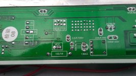
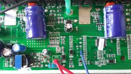
Can someone PLEASE tell if these are the proper pcb pads to jumper, or what I'm looking for?
The 64v pads are already jumpered and I'm assuming I add the pot there?
Or maybe replace that thing that's beside the 64v pads with the pot????
ANY details/info will help!!!!!
Also, I'm only assuming the simplest approach to be a trimpot so you can dial it in and/or change it later?
What kind of trimpot is necessary? Does it depend on what you're starting with or is it generic for all generic xiechang controllers?
As an alternative I'd even accept just eliminating LVC alltogether but that's far from ideal since we're not running an actual bms
. . .
Current LVC is supposed to be 42v but that seems like a soft LVC.
Hard cutoff is more like 40v accordign to my meter.
I want to drop to around 31.5v and be able to tweak slightly later. Thanks!
How to add a trimpot or permanently change LVC on this (or any) controller. I'd think there'd be a wiki or youtube entry that covers at least the basics but haven't found that to exist. Yet.
http://www.ebay.com/itm/48V-1500W-Electric-Bicycle-Brushless-Motor-Controller-For-E-bike-Scooter/132039821755?ssPageName=STRK%3AMEBIDX%3AIT&_trksid=p2060353.m2749.l2648
It appears to be a basic xie chang 18fet . . . .


Can someone PLEASE tell if these are the proper pcb pads to jumper, or what I'm looking for?
The 64v pads are already jumpered and I'm assuming I add the pot there?
Or maybe replace that thing that's beside the 64v pads with the pot????
ANY details/info will help!!!!!
Also, I'm only assuming the simplest approach to be a trimpot so you can dial it in and/or change it later?
What kind of trimpot is necessary? Does it depend on what you're starting with or is it generic for all generic xiechang controllers?
As an alternative I'd even accept just eliminating LVC alltogether but that's far from ideal since we're not running an actual bms
. . .
Current LVC is supposed to be 42v but that seems like a soft LVC.
Hard cutoff is more like 40v accordign to my meter.
I want to drop to around 31.5v and be able to tweak slightly later. Thanks!

