Xtracycle Edgerunner rear torque arm

ido

1 mW
Joined
Nov 1, 2015
Messages
12
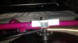
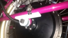
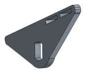
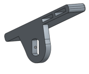
Hi all. I'm putting on a DD rear hub motor on my Xtracycle Edgerunner 11i. I haven't had any luck finding a rear torque arm for sale for the Edgerunner so I'm trying to design my own. Here's what I came up with so far with my 3D printer.
torque arm.png
View attachment 2
torque arm2.jpg
torque arm3.jpg
Before I have this thing fabricated out of stainless steel, I thought I'd see if anyone can spot are any issues with the design.
 
I think it would be better if the D hole part was right up against the dropout instead of having the nut between them. You'd be twisting a much shorter portion of the axle. Otherwise it looks good.
 
Unnecessarily complicated in unuseful ways.
TA at the end of the axle is not good. If that's a grub screw in there, it's not going to do anything useful.

If you use a conventional design with the TA sandwiched between the nut and dropout, then when you crank down the nut the vertical plate will held firmly against the dropout in the vertical plane and will only be able to rotate so your efforts need only prevent rotation. That right angle foot is unnecessary and doesn't give any advantage regarding rotation - it's just more expensive to fabricate.

The Mundo has similar dropouts, albeit somewhat larger. Something from flat plate like Kiwi's Mundo TAs should do as a model. If you want a band clamp, then slot the flat plate as is done with other commercial TAs (see ebikes.ca TAs). This would fit okay on both sides.
https://endless-sphere.com/forums/viewtopic.php?f=31&t=31881#p472405

A quick hack of your illustration....

torque arm.png
 
Please post a performance review once you get this all together, I'd like to read it. I have a cargo/utility bike too although with a mid-drive and am always curious to hear about how different systems work out.
 
Looks pretty good, but I agree with Tek': TA should always go against frame.

Another question, does it allow the axle to fully sit in the dropout? Looks a bit shallow, but that could just be the image angles.
 
Thanks for the valuable feedback. I'll redesign the TA and post an update. I'm a beginner and really appreciate the help.

999zip999 said:
That will work ticker the better and with norlock washers. Are you going to use regen.
I've never heard of norlock washers. Are they better than loctite?
Definitely using regen. I'll be pulling >150lbs several times per week in a hilly area and I wanted to save the brake pads.

999zip999 said:
Yeah give up the info Muxu's what 3000 @ what voltage and amps ?
I'm using an EM3ev 50V 14S7P pack. I believe it's current limited to 35 or 40A (can't remember).

cal3thousand said:
Another question, does it allow the axle to fully sit in the dropout? Looks a bit shallow, but that could just be the image angles.
IMG_20170824_163353891.jpgThere's about 2mm of space between the dropout and the axle. Should I file the dropouts down?

Raisedeyebrows said:
Please post a performance review once you get this all together
Sure thing.
 
ido said:
I've never heard of norlock washers. Are they better than loctite?

They're actually called Nord Lock washers. See here:
https://endless-sphere.com/forums/viewtopic.php?f=7&t=22585
the video there is unavailable, but the basic function is here
https://www.youtube.com/watch?v=tfkxN13bimw
and there's more here
https://www.google.com/search?num=100&newwindow=1&biw=1529&bih=925&tbm=vid&q=http%3A%2F%2Fwww.youtube.com%2F+nord+lock+

They work better than loctite, because you can undo the nuts easily enough yourself without heating anything, but they won't let the axle nuts come loose on their own.


Definitely using regen. I'll be pulling >150lbs several times per week in a hilly area and I wanted to save the brake pads.
Makes a huge difference to the pads on my SB Cruiser trike, or CrazyBike2.

But beware that if your regen is hard and sudden, the repeated torsion on the axle can eventually break them. This plus a final shock from a pothole snapped my X5304 axle recently. Seems to partly depend on which batch of recycled junk pot metal they made your particular motor's axle out of that day. ;)

If you have a controller that can do variable regen, rather than just on/off, it's easier on the axle/dropouts/etc and it's better control over braking.


I'm using an EM3ev 50V 14S7P pack. I believe it's current limited to 35 or 40A (can't remember).
FWIW, that's barely enough to start to nudge towards waking up the MXUS 3k / 45H series. ;) I'm using a 4T (previously a 3T) on the left side of SB Cruiser, with a 12FET 30A (33-35A peak) controller, on a "52v" (58v full) 14s2p 40Ah NMC pack (that could handle 100-200A if it had to), and while it's perkier than the 3T on the same setup, it would definitely perform better on a higher current controller.

Also, the battery current isn't the same as the controller current--what controller are you using?


BTW, are you sure yours is only a 50V pack? At 14s, unless it's LiFePO4, I'd expect 57-58V fully charged. They're often called "52V" packs instead of "48V" because 52V is around the middle of it's discharge curve.

13s is usually called "48V"


There's about 2mm of space between the dropout and the axle. Should I file the dropouts down?
The more perfectly the axle fits in the dropout, the better, as then there's one more thickness of metal to resist twisting, closer to the root of the axle. And the closer the axle is to the root of the dropout, the less it can force the tips apart. Just don't leave any sharp corners as those are weaker areas that can initiate cracks or tears.
 
I had a chance to review my orders. Here's what I got:
MXUS "3K-Turbo" (V3) 45mm Motor - 3T (11.9Kv)
18FET 80A/95V Sine Wave Xie Chang Controller
Cycle Analyst V3 Direct Plug
EM3ev 14S 5P battery pack, 40A continuous, 80A peak
 
ido said:
I had a chance to review my orders. Here's what I got:
MXUS "3K-Turbo" (V3) 45mm Motor - 3T (11.9Kv)
Since you already have it, this might not be helpful, but since I have tried both on my trike now:

The 3T is meant as a "speed" motor (vs the 4T). If you want more torque at startup, I'd go for the 4T. If you want more speed, keep the 3T. I found the 4T definitely better for me, since it's speed on 14s tops out just above my max allowed speed anyway, and has more startup thrust (which I need, partly to get out of the way of traffic starting up at intersections when I'm stuck in front of them).

The 3T should peak out around 32MPH, but only start out with around 70lbs of thrust from a stop (with 40A system current limit).

The 4T shoudl peak out around 24MPH, but will start out with around 90lbs of thrust.


This is a comparison of the two motors at 40A
http://www.ebikes.ca/simulator2/?bopen=true&motor=MX4503&motor_b=MX4504&batt=B4823_AC&hp=0&frame=mountain&mass=150&wheel=20i&cont=C40&cont_b=C40&batt_b=B4823_AC&wheel_b=20i&mass_b=150&hp_b=0&axis=mph&blue=Lbs

I'm not sure what phase amps you'd have with the 80A controller, so not sure what to put in the simulator for that, but with 140A phase then it goes way up in startup torque, though speeds stay the same.

http://www.ebikes.ca/simulator2/?bopen=true&motor=MX4503&motor_b=MX4504&batt=B4823_AC&hp=0&frame=mountain&mass=150&wheel=20i&cont=cust_80_140_0.03&cont_b=cust_80_140_0.03&batt_b=B4823_AC&wheel_b=20i&mass_b=150&hp_b=0&axis=mph&blue=Lbs

18FET 80A/95V Sine Wave Xie Chang Controller
Cycle Analyst V3 Direct Plug
EM3ev 14S 5P battery pack, 40A continuous, 80A peak
How long can the battery pack hold that 80A?

Cuz you said you have hills, and with an 80A controller, unless you use the CA to limit the max current, or the controller is programmed otherwise, or physically modified to reduce it's max current, you could end up pulling that 80A all the way up the hill depending on the load, hill, and speed you're attempting to keep up.

Assuming no limiting takes place, then how the battery responds to that depends on it's BMS. If the BMS has an overcurrent protection that kicks in when over 40A for a few seconds, then you'll lose power on the hills that take more than that. If it does not have overcurrent protection then it will begin heating the cells, and how long it does that will determine if problems occur because of it.

If you parallel two of the packs, it wouldn't be an issue (unless one of them runs low faster than the other and you're near the end of capacity for them on a long trip), but that's more space and weight on the bike (and cost to build). On the plus side, it'd at least double your range, though. Oh, and make takeoffs a bit faster, hill climbs a bit easier, because voltage won't sag as much under load.


Since you have the CA v3, though, your best option is to use it's limiting features to throttle back the controller so it doesn't go above 40A. (or if you have the option to limit it after a certain amount of time, to set that time to a very minimal amount so you can get a boost on startups from a stop but not longer than that).

There are specifics on how to set limiting (and everything else) up in the Unofficial User's Guide by Teklektik, latest version at
http://www.ebikes.ca/product-info/cycle-analyst-3.html
https://endless-sphere.com/forums/viewtopic.php?p=571345#p571345
 
Thanks for the helpful info. 32 mph sounds about perfect for me, but we'll see if there's enough pulling capacity.
amberwolf said:
How long can the battery pack hold that 80A?
Not sure, probably till the battery blows up. But each hill climb is only about 10 min long, so I don't think the battery pack will get too hot. I'm looking foward to messing with the CA once I get the motor mounted.
 
Well, if the battery blows up then it didn't really hold that current (in that being able to hold it means it can handle it without damage or failure).

What I meant (but wasn't clear enough about) was: How long will this particular BMS allow the pack to supply 80A before it shuts down? And what are these specific cells rated for from the cell manufacturer?

If it doesn't shut down, and you don't limit it some other way, it doesn't take long to start stressing the cells, if they're not designed to handle the load. If the cells are capable, but the BMS is not, it's output FETs could get too hot and either fail or desolder themselves (and that could lead to shorting internally in the pack or even a fire depending on where solder and bits go).

If neither of these happens, and boht cells and BMS are capable of the 80A without harm, it'll still have more (probably significantly more) voltage sag.

When the pack is full it just means top speed is lowered. When the pack is getting closer to empty it could cause the BMS to shutdown to protect against low cells even when they have plenty left in them. When this happens it'll usually recover as soon as the load is removed (throttle is let off), but once the load is restored to the tipping point it'll shutdown again.

As for a 10 minute 80A load on a 40A continuous battery...if the BMS doesn't shut it down, one way or another that's almost certainly more than the pack can take.

Normally "burst" or "peak" loads are intended to be a few seconds long, but I don't know how long EM3EV rated that pack to do double it's continous rating.


I'm only bringing it up at all because I don't want you to get stuck with a problem that could've been prevented--especially one that could potentially result in dramatic failure modes (even if it's more likely to just lower the lifespan of the pack).

Hopefully it won't be a problem...but knwoing it might be, you can verify and test for this sort of thing, and prevent it. :)


BTW, speaking of thermal limits, your motor should have a temperature sensor installed in it from MXUS. If it's the right type, you can hook that to the CA to allow it to do thermal limiting, rolling back the power level when the motor gets too hot. Alternately you can put a temperature sensor in the pack's core, and have it rollback based on that.

Even if you don't limit anything from it, you can still monitor the sensor in the motor, either via teh CA or a separate display. You can also use those cheap BBQ thermometers, eiether the wireless remote type or the wired ones. Put the display on the handlebars and watch the temperature as you test teh bike in different ways.
 
Some more tidbits, pondering, and questions:

I don't know that your system will actually even pull 80A on the hills you have; you can probably use the Trip Simulator at Grin Tech to get an educated guess before you test it.


FWIW, if you really did pull 80A from the pack for 10 minutes, you'd use over 13Ah right there. 10min = 1/6hour, 80A * 1/6h = 13.33333Ah. Hopefully your hills aren't steep enough to require that. ;)

According to the EM3EV page, if I found the right pack there, it's only a 14.8Ah pack to begin with, so at that rate you'd not have much range.


Which pack exactly do you have? Is it one on this page?

https://em3ev.com/shop/50v-14s5p-rectangle-battery-pack/

If so, and it's the 80A variant in the chart down the page, then it should be built with "High Power – 30Q" cells. It'll also be a 14.8Ah pack, whcih means that 80A is over 5C, but a note on that page says they're rated at 5C.

This should be the spec sheet for those
https://eu.nkon.nl/sk/k/30q.pdf
whcih shows max continous discharge per cell of 15A (at 25°C, will have to be lower as it gets hotter), but that this reduces it's lifespan so it will only have 73% of it's original capacity by the time it's gone thru 300 charge/discharge cycles. A further indication later on says it'll only get you about 97% of whatever capacity it's charged to at that high a current.

So the cells themselves can supply 80A in 5P, though IIUC the spec sheet they'll have at least a .2v drop per cell at that rate (2.8v for the whole pack).

But I dont' see anything on the EM3EV page about what the BMS specs actually are (or what the pack-level fuse is rated at for amps and time).
 
Just a quick update. I redesigned the TAs and they look pretty much identical what teklektik suggested.

I also got quotes from different shops in my area to fabricate the torque arms. This is the first time I've ever order parts to be fabricated. Prices were all over the place and the best price I got was to water jet 4 pieces for $100 from 1/4" 304 stainless steel. If everything goes as expected, I'll receive the parts in about a week, realize my measurements were off, then order another batch.
 
I think you will be happy with the approach.

If you have or develop a little fore and aft rocking slop, then you might slip a washer or two between the TA and the dropout to move the TA outwards towards the center of the chain stay. The curvature of the stay relative to the stay/dropout attachment is such that the shimming will reduce the clearance between the TA and the stay and eliminate the play. Might save you the cost of a second modified run if that particular fitment is an issue.
 
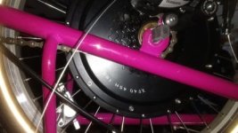
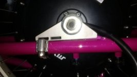
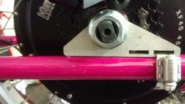
Here's another update. The TAs came in and they look pretty good, but I don't know how tight fitting they need to be. You can see there's a slight angle on the motor wire side.
View attachment 2IMG_20170905_171349515.jpgIMG_20170906_113504166.jpg
 
The fit depends on whether or not you plan to use regen which will torque the TA in both directions - rocking the TA will tend to work the nut loose. If so, those look too loose.

  • Properly installed, Nordlocks will resist loosening, but they don't work well tightened against a hard metal in which they cannot bite. See this post: https://endless-sphere.com/forums/viewtopic.php?f=3&t=81802&p=1202917#p1202857.
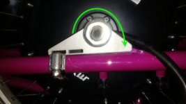
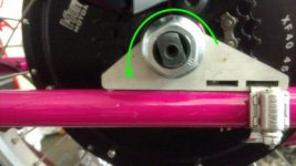
In a related vein - the motor torques the TAs in the direction opposite that of wheel rotation. So in your case we have this situation:

IMG_2.jpgIMG_3.jpg

Here we see that the force of motor torque is being restrained entirely by the band clamp because of the loose fit - NG. Ideally, you want the force to transfer directly to the frame from TA. This could be remedied by flipping the TAs over so the clamps are on the other side of the dropout. In that case, in normal forward powered motion, the clamp wouldn't really be doing anything and the TA would be rotating into the chain stay. Hopefully there are no fitment issues with the present TA design.

With no bolt to secure them, this particular Kiwi-esque design does require a snug fit for regen use. I mentioned in a prior post a washer-shimming approach that might do the job, If that doesn't work out, I would recommend another batch with the foot of the TA a bit further from the axle hole. It might be a good idea to make this measurement a mm or so too large so the axle doesn't (currently) seat 100% in the dropout. As the chain stay/TA interface gets a mooshed over time, the axle will just seat a little deeper so no slop in the seating will develop.

As Cal3K mentioned above, you probably needed to file you dropouts. Unfortunately, that motor shaft is pretty big compared to the dropout - not a lot of extra material there so you may need to compromise over an ideal centered axle fit. Here are two posts/threads that you may find useful - they relate to filing the dropouts to get better axle seating and to get the axle centered in the depression so you can add a inner washer and have it lie flat against the dropout.

https://endless-sphere.com/forums/viewtopic.php?f=3&t=82721&p=1213888#p1213921
https://endless-sphere.com/forums/viewtopic.php?f=3&t=75857&p=1145413#p1145413

The segue here is that you might be able to eliminate the present gap by filing the dropout deeper, but if you've already fit it as best you can, then that approach is likely off the table.
 
ido said:
Here's another update. The TAs came in and they look pretty good, but I don't know how tight fitting they need to be. You can see there's a slight angle on the motor wire side.

It looks OK to me. I don't think the gap will affect the strength. With dual arms, it should be more than adequate for that motor.
 
Hey ido, I'm trying to do almost the exact same thing (add a rear hub motor) to an Xtracycle Swoop, which has identical dropout geometry afaict. Do you think you could share the CAD file and fabrication details?
 
Back
Top