Destroyed my CA3?

tanstaafl

10 W
Joined
Apr 21, 2017
Messages
92
I guess I've destroyed my CA, unless somebody can suggest something else to try. It was working fine until I decided to add a speed sensor so I could use a MAC motor instead of the cheap direct drive motor I got in an ebay kit. I've done a lot of soldering and wiring in the past, so I didn't really think I'd have any problems, but I've messed something up. I've even removed the sensor and looked carefully at the board (bright light, magnifying glass, etc.) and don't see anything wrong, but the problem persists.

When I plug in the CA and then power on the controller, it seems to start coming up OK, but as soon as it gets past the immediate startup screen, it starts going crazy, like I'm pressing buttons on the front. The most common display says "Trip Reset", but it goes through lots of other screens as well. It's not the buttons themselves, I've also tried unplugging the little ribbon cable that goes to the buttons and I still see the display jumping around.

I'm ready at this point to just throw it away and just buy a new one. Which really gets me PO'd. I'm decent at this kind of stuff -- I've done a little hobby work like this for decades. And I can't see anything at all wrong with the board. No bridged traces, stray bits of solder or wire, melted insulation, etc. I've even removed a couple of the other wires from the controller (ground, power) and re-soldered them to make sure there wasn't some kind of hidden short or loose connection somewhere. I _should_ have just sold the CA on ebay instead of messing with it and just bought a new one with a speed sensor already wired in. I did the work (and now a lot of time "debugging" it) and I have less than I started with.

To top it off, I'm not thrilled with the new motor that was the reason for the change in the first place! So far, of course, I'm stuck using it without the CA (with throttle hooked up directly to my Grinfineon controller), but that's got nothing to do with the my unhappiness with the motor. Basically, it's just a lot louder than I thought it would be - a constant clicking noise when running. And when I release the throttle, and wheel is slowing down, I hear a high pitched whine until the wheel stops. It's probably a great motor and I won't find the noise objectionable out on the street, but in my living room testing, it seems irritating. Or maybe I'm just in a bad mood because of the other problem...
 
tanstaafl said:
When I plug in the CA and then power on the controller, it seems to start coming up OK, but as soon as it gets past the immediate startup screen, it starts going crazy, like I'm pressing buttons on the front.
I'm not sure anymore, but I think the button common is ground. You can check this easy enough. If it is, what happens if you use a resistor across the button input and the internal 5V (or 3V? sorry I don't recall) for each button? (if it's not ground, and is +V, then put the resistors to ground from the buttons).

If this stops the craziness, then it might be the internal pullups (or pulldowns, if the button common is +V) causign the problem somehow (lifted trace or pad, cracked via, etc).


a constant clicking noise when running.
Could that be the freewheel on it (if it's a rear motor)?

If not, perhaps it's something in the spokes (or even a loose nipple floating around inside the rim).


And when I release the throttle, and wheel is slowing down, I hear a high pitched whine until the wheel stops.
That kinda sounds like the clutch in the motor is not freewheeling, and the motor is being spun by the wheel mass-inertia. You can test for this by putting a voltmeter across any two phases. Once the throttle is released the voltage should drop to zero. If it doesn't, the motor is still spinning inside the hub (it shouldn't, since the MAC is a freewheeling geared hub).
 
It seems clear the CA believes the buttons - or at least the right button - is being pressed.

This looks very much like a floating processor input. The button inputs are pulled up by 100K resistors R1 and R2 near the button connector pads and pulled to GND by a button depression. The resistors are out of the way of the Spd signal you altered so it's difficult to see how they or their connections could have been damaged. There should be nothing happening if the button assembly is simply disconnected - but you report that symptoms persist so the button assembly is not the culprit. Since there's essentially no button circuity to go awry and you report having inspected the PCB for shorts, etc -- as unlikely as it sounds, this might just be a static zap from handling the board that took out a processor input pin.

As always, I recommend as a first step to contact the manufacturer instead of coming to a public forum. This gets you authoritative assistance and a quick evaluation of your repair/replace options. An email to Grin with a reference to this thread (since you've already told the tale here) and a query about specific options they could offer would be the best plan. Justin is away until next week, so there might be a bit of a delay if this matter gets bumped up to him. Grin has excellent Tech Support and you paid for it when you bought the device - use it. :D
 
tanstaafl said:
To top it off, I'm not thrilled with the new motor that was the reason for the change in the first place! So far, of course, I'm stuck using it without the CA (with throttle hooked up directly to my Grinfineon controller), but that's got nothing to do with the my unhappiness with the motor. Basically, it's just a lot louder than I thought it would be - a constant clicking noise when running. And when I release the throttle, and wheel is slowing down, I hear a high pitched whine until the wheel stops. It's probably a great motor and I won't find the noise objectionable out on the street, but in my living room testing, it seems irritating.
Not sure what's going on there, but this is not how MACs sound or work. Should be essentially silent save a little gear noise that will ease up after some miles as the gears wear in.

EM3EV ships motor/wheels partially disassembled - so unless you accidentally introduced some bit of poo into the guts when assembling the motor, this sounds like a freewheel and/or possibly a dragging brake rotor issue. Anyhow - it's not a normal MAC sound.

Cheer up - this one should be fixable w/o too much trouble.
 
teklektik said:
As always, I recommend as a first step to contact the manufacturer instead of coming to a public forum.
If I were complaining about the manufacturer, you'd be perfectly correct. Since it's certainly something I caused, I'd rather not bother them any more than I have to (though I may have to if I can't figure this out).
 
amberwolf said:
tanstaafl said:
When I plug in the CA and then power on the controller, it seems to start coming up OK, but as soon as it gets past the immediate startup screen, it starts going crazy, like I'm pressing buttons on the front.
I'm not sure anymore, but I think the button common is ground. You can check this easy enough. If it is, what happens if you use a resistor across the button input and the internal 5V (or 3V? sorry I don't recall) for each button? (if it's not ground, and is +V, then put the resistors to ground from the buttons).

If this stops the craziness, then it might be the internal pullups (or pulldowns, if the button common is +V) causign the problem somehow (lifted trace or pad, cracked via, etc).
Good call on the pull-up resistor. Left button is pulled up, right one isn't. I checked voltage with the unit powered on, then checked resistance with the power off -- ~150K to left button (from +), 1.5M to right button. Strange.
teklektik said:
The resistors are out of the way of the Spd signal you altered so it's difficult to see how they or their connections could have been damaged.
I agree, but maybe I somehow cracked something putting it back together. It's strange. I'll try pulling up the right button and see if the problem goes away, I guess. I just have to find a small resistor.
 
I unsoldered a a pair of cable bundles on one of my CA's and now putting them back on. Its a challenge not to bridge the pads with these old eyes.
 
Triketech said:
I unsoldered a a pair of cable bundles on one of my CA's and now putting them back on. Its a challenge not to bridge the pads with these old eyes.
+
The wires are almost too big for those pads. Luckily, I have a decent soldering iron now -- my old one had a tip that was too big for such tiny pads.
 
amberwolf said:
And when I release the throttle, and wheel is slowing down, I hear a high pitched whine until the wheel stops.
That kinda sounds like the clutch in the motor is not freewheeling, and the motor is being spun by the wheel mass-inertia. You can test for this by putting a voltmeter across any two phases. Once the throttle is released the voltage should drop to zero. If it doesn't, the motor is still spinning inside the hub (it shouldn't, since the MAC is a freewheeling geared hub).
If I spin the wheel by hand, in a forward direction I get 0 ac volts. If I spin the wheel in the reverse direction, I get a voltage. Is this what I should expect?

The clicking noise is from the freewheel. It sounds loud in my living room, but I guess it won't be objectionable out on the road. First, I will usually be pedaling. Second, while my bike's original rear wheel was much quieter, I've heard regular bicycles that are nearly as noisy. Still not sure what the faint whining noise was when I released the throttle. I should have mentioned in the original post that the whining noise is very faint, not loud like the clicking.
 
iirc, adding a speedo was as simple as adding one wire to one fresh pad, and jumping another with the second wire. I think I had to move or clip an existing lead as well. Eitherway, if your trouble arose from there it really should be a straigtfoward issue/fix. unless a semiconductor inexplicably got semifuct?

Btw that's a nice user name. I got a free lunch from the dumpster the other day, and also one from the river, but I know that's counter to point lol.
 
tanstaafl said:
If I spin the wheel by hand, in a forward direction I get 0 ac volts. If I spin the wheel in the reverse direction, I get a voltage. Is this what I should expect?
Yes. So nothing wrong with the motor's clutch.

Still not sure what the faint whining noise was when I released the throttle. I should have mentioned in the original post that the whining noise is very faint, not loud like the clicking.
Best bet is to put your ear to various areas on the rear wheel, from the motor to tire to rim to brakes, etc. Could be something as simple as edge of a tire just barely touching the edge of the frame, or brake pad just touching rim, etc.
 
I tried a 100K resistor between +V and the left leg of the button's ribbon cable and it seemed to work. I haven't soldered it in yet, but I'm cautiously optimistic. I'll probably do it over lunch, since we have a nice soldering station here at work. Thanks to everybody for the helpful suggestions.
 
Yep - sounds promising....
If you are tacking on a repair using a regular wire lead resistor, just jumper the other side to either the ThrottleIn or AuxPot +5V pads. These are switched +5V power controlled by the processor the same as the original pull-up +5V. Either sleeve the whole reistor and leads in heatshrink or slip a bit of stripped wire insulation over any exposed resistor leads on the way to the +5V pads (stuff gets pretty well squashed fitting the case back together).

Don't worry about the failed SMD pull-up -- even if it's intermittent or is somehow magically restored in the future by vibration, etc, it won't have an adverse effect on operation with the new 100K installed. So - I wouldn't recommend trying to remove or otherwise messing with the existing SMD parts/traces in an attempt to tidy up - just add the new resistor and let sleeping dogs lie.... :D
 
teklektik said:
Don't worry about the failed SMD pull-up -- even if it's intermittent or is somehow magically restored in the future by vibration, etc, it won't have an adverse effect on operation with the new 100K installed. So - I wouldn't recommend trying to remove or otherwise messing with the existing SMD parts/traces in an attempt to tidy up - just add the new resistor and let sleeping dogs lie.... :D
That was my plan. With my luck, removing the old resistor would leave a solder bridge or something... :roll:

This time I will wait to add the silicon seal until I've used the thing for a few days and verified that it works. :oops:
 
teklektik said:
Justin is away until next week, so there might be a bit of a delay if this matter gets bumped up to him.

That's true, although long airport layovers like this can provide excellent opportunity to get caught up!

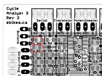
Anyways it looks like tanstaafl has got things sorted out OK. For the record, the actual SMT pull up resistors are R1 and R2 on the top left of the PCB, just beside the button header, in case you wanted to look into what actually opened up.
CA R1 and R2.jpg
The right pads of R1 and R2 are the 5V bus
 
Unfortunately, my CA is well and truly dead. I appreciate the help from everybody, but I screwed it up. A wire came loose after everything was working fine and the case had been sealed back up. It released the magic smoke that makes electronics work, and my CA is no more. RIP.

I'm back to my original thought when I first had problems -- I shouldn't have invested the time and effort to add the speed sensor to my CA 3 that was in perfect working order. I should have sold it (I could have gotten a very large portion of the original cost back) and just bought a new one with the speed sensor.
 
tanstaafl said:
Unfortunately, my CA is well and truly dead. I appreciate the help from everybody, but I screwed it up. A wire came loose after everything was working fine and the case had been sealed back up. It released the magic smoke that makes electronics work, and my CA is no more. RIP.

I'm back to my original thought when I first had problems -- I shouldn't have invested the time and effort to add the speed sensor to my CA 3 that was in perfect working order. I should have sold it (I could have gotten a very large portion of the original cost back) and just bought a new one with the speed sensor.

It's still quite often possible to put the smoke back in and resurrect electronics from the dead. Open it up and tell us what is the actual part that is fried.
 
I don't have a picture with me, but I did tear it apart last night. The ground wire popped loose from the board and there's a "burnt" spot on the board about the size of a penny starting just above where it would connect. It looked like the pad came loose from the board. Too much heat? Physical damage from all the handling as I tried to figure out the earlier problem? Perhaps the board could be saved, but I'm guessing I'm not the person to do it. At this point, I just want to get my new bike finished with as little additional labor on my part as possible. I've been working on the thing for weeks...

I've already ordered a new one and I expect to be using the old one for spare parts (connectors, replacement buttons, replacement screen, etc. Spare parts are always useful, I guess.

Thanks again for all the help from everybody.
 
It's actually still alive! It's hard for me to believe, but I actually got it to power on. There's a big scorch mark on the board and the ground connection is just gone. The polyfuse is half burned off the board and other stuff looked "scorched". The incoming power wires have melted insulation and some of the other wires don't look that great. But I managed to get the board to power up by connecting the ground and power to where the power goes out to the output power jack. If the fuse isn't dead, but just has one leg burned through, I can probably solder it back together (or just replace it -- they're not that expensive but S&H for one polyfuse is probably some stupid amount). Then I will have to use another location for ground connection (probably that output power jack ground pad). Given all the abuse I had given the board, I didn't really expect to get this back working. But after I got my other (newer) CAv3 set up the way I wanted, I decided to give it a try.

I'm not sure all the features will work, but if the majority of the damage is around the polyfuse, maybe other stuff is OK-ish. If it is, this is a real testament to how resilient the CA is.
 
CA3 dead.jpgAnother dead CA3?? as I've posted before my Quattrovelo velomobile has a converted Smart Pie motor (fixed and driving through the normal chain and gears) with a Grifineon 25A controller and CA3.(using thumb throttle, wheel speed sensor,motor temp sensor, and analogue aux pot) and It all worked perfectly until recently when I rode over a particularly bumpy UK road causing a failure of the Grinfineon mounting which momentarily hung on its wires) I did a temporary restraint of the controller and rode home without any problems. Next day I was about to set off on a ride and although the CA3 booted up there was no drive to the motor. On careful inspection I found one broken wire (on Controller to the motor sensor plug so I resoldered this- the YELLOW one) Sadly on repowering system the CA3 failed to boot up-- no indications at all!
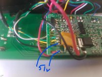
I've since minutely examined all the connections and opened the CA3 and Grinfineon to check for any sign of loose wires or melted solder. Everything seems OK and power(51V from 48V battery( is available to the PCB in the CA3 via the Grinfineon CA-DP plug (see photo) but the CA screen remains blank. Any suggestions??
 
If you disconnect the CA from everything, and just supply power to it (via the red black wires in the CA plug, or where your 51v is marked is in the pic), does the behavior change?

If so, it means there is something in one of hte ohter signal wires to it preventing normal boot.

If not, then if the hall sensor plug wire happens to also be the one used for the CA speed sensor wire, then if that wire shorted to any of the phase wires or other higher votlages (either at the CA plug, at the mtoor axle exit inside the cable, or inside teh controller, for example), it could've damaged the CA's MCU (and probably the motor's hall sensor). This happened to me a few years ago; I haven't yet gotten the CA sent to Grin to fix (because it probably needs at least a new MCU and I don't know that I could do that kind of fine work anymore).


Also possible that somehow the CA's regular power supply got damaged. If that's the case, you can run it temporarily off of a low voltage supply like 12v, to test it.
https://endless-sphere.com/forums/viewtopic.php?f=2&t=19540&p=679054#p678269
To see if the rest of the CA is fine, just apply 12V power directly to where the output of the mosfet would normally be (or to the LED+ pin on the LCD header). If all is well it should power up to the splash screen fine, though it would then enter shutdown mode after that since the measured VBatt would be close to 0V
 
Thanks for the reply!
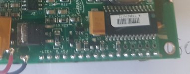
I originally powered the main black and red wires via the Controller(from the battery)- using the normal plugs as fitted but with no other wires connected--as I said that gave me battery voltage at the pins shown in the earlier photo. After your reply I tried feeding 12V (from another battery) directly to the LED +/- headers - shown in the picture attached to this post. The screen illuminated but NO TEXT of any sort- it stayed illuminated as long as the power was connected (actually about 13.5V) What would this indicate?2018-08-06 15.34.19.jpg
 
If it's connected with battery ground to the CA battery ground, and the battery positive to the LED +, then it means the MCU is not able to boot at all; otherwise it should at least give you the Low Voltage message.

That could be from damage to the actual MCU (which AFAICT is what's wrong with mine), from a short causing phase or battery voltage to go into the speed sensor / hall wire on the CA connector, from the motor to the CA PCB.

I'd talk to Grin Tech support about it, and see if they can fix it.

If it helps, the link I gave has a schematic of the low voltage power section.
 
Thanks again Amberwolf- I'll try this today and report back. I hadn't thought of using the main earth connection- of course using the LED +/- means I hadn't powered the main "MCU" ??
 
I tried your suggestion today- used the LED+ together with a common ground (not LED- this time) The screen lights up with the message "SLOW PMR UP" I assume this means that the MCU is OK? Now I guess I need to try with everything plugged back in and see what happens-- just hope that the Hall sensors in the motor haven't fried?

Since then I tried powering the CA3 directly from the 48V battery with nothing else connected- no response (not booting at all)=> power supply failure??

I've also tried powering the Grinfineon without the CA3 but with the throttle and HALL plug plugged directly directly into it. The LED on the controller flashes MOST of the time indicating sensorless operation and the motor runs-- randomly the LED goes steady indicating that it's in sensor mode- I guess this suggests either a Hall sensor's failed or an intermittent cable fault.

It seems as if there is more than one fault which makes diagnosis tricky- at the worst I would have to replace BOTH controller and CA3- an expensive fix!
 
Back
Top