
mateusleo
1 kW
I have this 220 V charger, but here on my region mostly outlets are 127 V, in fact, I had to install a 220 V outlet just to use this charger.
So today I decided to open it and I figured out that the rectifier in the input could be transformed into an voltage doubler, so even though the grid power is 127 Vac, there will be still 360 Vcc on the voltage doubler output. With 220 Vac and the initial rectifier, there would be 311 Vcc on the rectifier output. This little difference will not damage the battery, because the switching circuit after that will keep the voltage at the level of your battery.
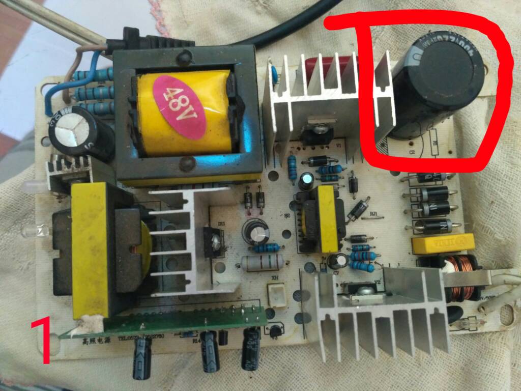
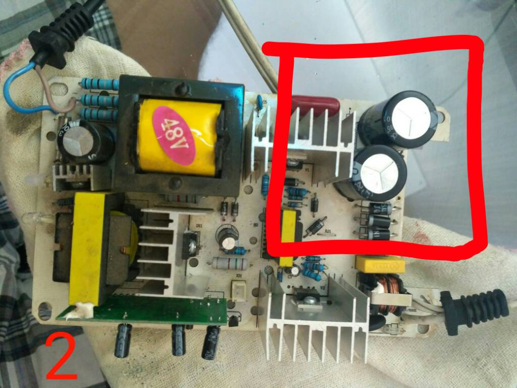
The mod is pretty simple (read warnings below before starting). First step is remove the big capacitor on picture 1. Second step is solder the 2 capacitors as shown in picture 2, these must be at least 330 uF and 200 V, recommended is 440 uF and 300 V. After soldering the capacitors, final step is solder the jumper pads shown in picture 3, on that image they are now soldered together, but all you gotta do is make a blob of solder joining the pads.
Done, your charger now will work on 110/127 V outlets.
WARNING 1: you can no longer use that charger in a 220 V outlet.
WARNING 2: pay a lot of attention on the capacitors polarity when soldering (on my PCB the polarity was printed on the top silk), else you could explode the caps, and it's extremely dangerous at such size.
WARNING 3: short circuit the capacitors on the charger with a screwdriver before touching it, there could be up to 311 V, which is a deadly voltage.

Enviado de meu Redmi 3S usando Tapatalk
So today I decided to open it and I figured out that the rectifier in the input could be transformed into an voltage doubler, so even though the grid power is 127 Vac, there will be still 360 Vcc on the voltage doubler output. With 220 Vac and the initial rectifier, there would be 311 Vcc on the rectifier output. This little difference will not damage the battery, because the switching circuit after that will keep the voltage at the level of your battery.
The mod is pretty simple (read warnings below before starting). First step is remove the big capacitor on picture 1. Second step is solder the 2 capacitors as shown in picture 2, these must be at least 330 uF and 200 V, recommended is 440 uF and 300 V. After soldering the capacitors, final step is solder the jumper pads shown in picture 3, on that image they are now soldered together, but all you gotta do is make a blob of solder joining the pads.
Done, your charger now will work on 110/127 V outlets.
WARNING 1: you can no longer use that charger in a 220 V outlet.
WARNING 2: pay a lot of attention on the capacitors polarity when soldering (on my PCB the polarity was printed on the top silk), else you could explode the caps, and it's extremely dangerous at such size.
WARNING 3: short circuit the capacitors on the charger with a screwdriver before touching it, there could be up to 311 V, which is a deadly voltage.
Enviado de meu Redmi 3S usando Tapatalk