Wiring for Multiple Controllers

Glyn

10 W
Joined
Oct 7, 2017
Messages
70
Hi all,

I'm, building a 6-wheel-drive vehicle using brushless ebike hub motors (20T 48v 500w 5:1 Mac - 10A continuous, 15A Max).
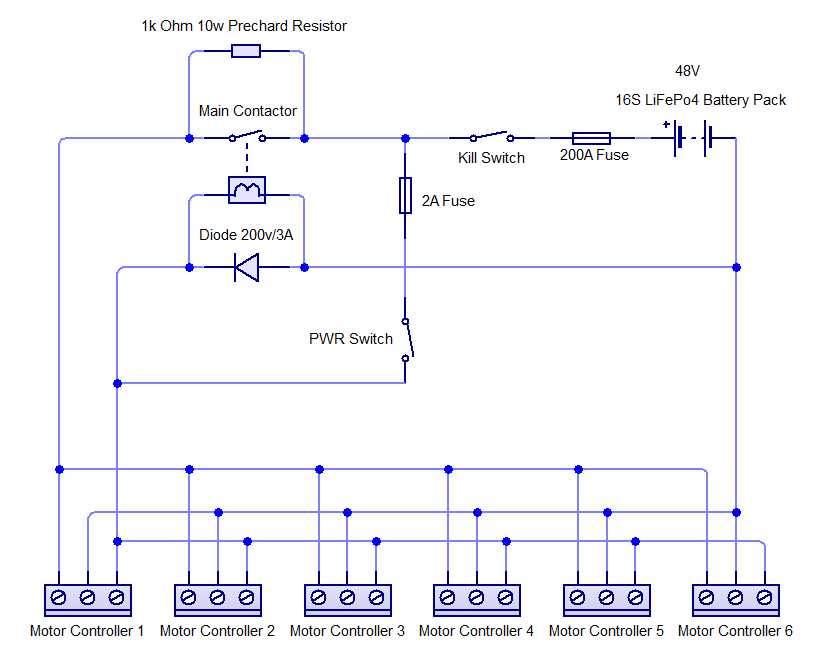
I couldn't find a brushless controller with 6 channels, so I've bought six single motor controllers instead. The 6 controllers are Kelly KBS48101X controllers.
They'll be running off battery packs made of 16 Headway cells (56.5v fully charged)

The vehicle will be driven tank style, with one joystick going to three controllers on one side, and vice versa.

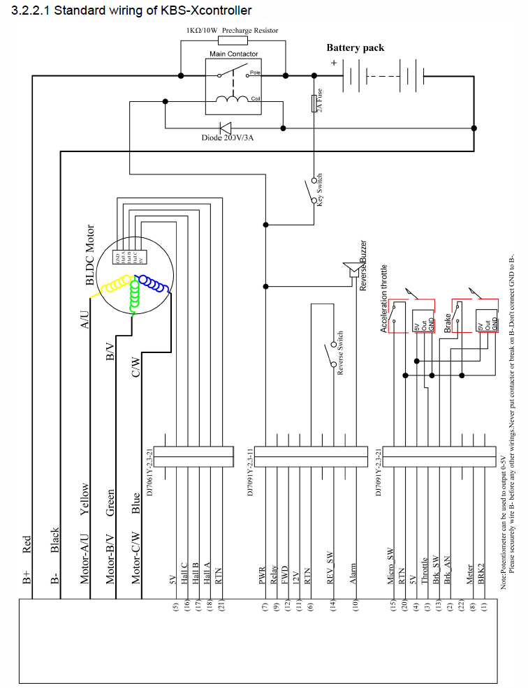
Looking at the wiring diagram in the user manual though, I have some questions.


You can see in the diagram that they recommend using a 1k Ohm 10w Precharge Resistor across the main contactor (see top of diagram).

I understand the precharge resistor is needed to fill the capacitors, otherwise the current draw is too large when you connect the battery which can weld the contactor. My first question is, do I need a contactor or can I use just a bog standard switch, and, if I just go with a switch, will it still need the precharge resistor?

I guess I'll wait for an answer to this question first but it will impact my next questions.
 
Glyn said:
I understand the precharge resistor is needed to fill the capacitors, otherwise the current draw is too large when you connect the battery which can weld the contactor. My first question is, do I need a contactor or can I use just a bog standard switch, and, if I just go with a switch, will it still need the precharge resistor?

Since you'll have six controllers' worth of caps to charge, there'll be six times the amount of current flowing at pack connection time, so a precharge is a good idea whether you use a contactor or not.

If you do use a precharge, I recommend having it switchable, so if you turn the whole system off it also turns off the precharge. Otherwise the controller is still connected to the battery, and if you leave it sitting for a few weeks or months (dpeneding on controller idle current), it can drain and kill the battery (unless the battery has a BMS to shut it off when low to prevent that, but then the BMS itself may kill the pack (at least some cells) if left in that low state for too long).

Also, it means the contrller is still active, and if someone accidentally hits the throttle it could do something (even if there isnt' sufficien current thru the precharge resistor to do much), which could surprise someone at the least. :)


That said, I don't use a precharge, on either SB Cruiser or CrazyBike2, with two controllers and a 14s NMC pack (58v full). But this does cause contact damage over time; if I hot-plug my battery (ANderson SB50 connectors) I can see/hear the pop/arc, and it leaves a little damage on teh tips every time. (the Anderson cotnacts are designed iwth this in mind, so ti doesn't affect their connnection, but on a switch it can and eventually does, unless the swtich is like the Andersons, with sacrificial tips and wiping contact surfaces).

On SBC, I'm using a common battery-disconnect as my switch. (one of those with a red T-handle you insert and twist 90 degrees to turn on, twist back to turn off and you can pull the "key" out, as theft protection or safety, etc). Been working a couple years like that, I guess it's been. Maybe less, cant' remember when I installed it.

On both SBC and CB2, I also have a circuit breaker I can flip as a switch, and on CrazyBIke2 that *is* my switch. It's survived for years without issue, and still works as a breaker, but there's never a guarantee that will continue. ;)


I also don't use a contactor, but that's mostly because I don't have one I can repurpose. :)
 
As always, thanks for the informative reply Amberwolf.

After spending some more time looking at the wiring diagram and taking what you said into consideration, I came up with this which eliminates the contactor and I think is far simpler than the Kelly version:


To make the diagram more readable, I've only included one controller for the moment, but other than that, what do you think?
 
Update
I think I've come up with the final wiring diagram for the 6 controllers (See below).

Essentially, it's exactly the same as the one provided by the manufacturer, with the addition of a kill switch (to prevent battery discharge as per Amberwolf's suggestion, and a fuse). I figured it was better to use a contactor rather than relying on my 11 year old daughter to operate the switches in the correct sequence.

Questions Arising
  • I've decided not to change the value of the precharge resistor. Kelly recommend using a 1k ohm 10w resistor. I thought the resistance might need to be reduced if I have 6 controllers all precharging off the one resistor. However, I needed to account for human error and consider what would happen if I lowered the resistance, and then powered up with only one controller connected (presumably it would pull too much current?). The controllers have a programmable precharge time of 0.5 seconds so instead of changing the resistor, I've just increased the precharge time to 2 seconds. I'd really appreciate some input on whether or not you think this is the right thing to do?

  • In terms of the diode in the diagram, I don't honestly understand what function it's performing. I mean, I understand a diode allows current to flow in one direction, I just can't see what function it's performing in the context of this diagram. If somebody could clear that up for me then I would be extremely grateful.

Although there are now 6 controllers attached, I've stuck with a 2A fuse before the power switch. The reason being that according to the manual it only draws 30mA on this wire so a 2A fuse seemed ample for all six controllers.

 
Glyn said:
I've decided not to change the value of the precharge resistor. Kelly recommend using a 1k ohm 10w resistor. I thought the resistance might need to be reduced if I have 6 controllers all precharging off the one resistor.
With six controllers, there is six times the amount of capacitance. So it'll pull six times the current thru that resistor, or take six times as long to fill them up, depending on whether you reduce it's resistance (to 1/6 of the given value) or leave it. If you reduce the resistance, you may need a higher wattage resistor, so it's easier to use six resistors to do it instead of finding one 1/6 the resistance and six times the power level.

Which way you do it depends on what you want to happen, budget, space, etc.


In terms of the diode in the diagram, I don't honestly understand what function it's performing.
It "shorts out" the coil's reverse voltage when you turn the contactor off. Otherwise the stored energy in the coil goes somewhere else in the circuit, potentially into the contactor driver circuit (which if it doesn't have a built-in diode could fail).
 
amberwolf said:
If you reduce the resistance, you may need a higher wattage resistor, so it's easier to use six resistors to do it instead of finding one 1/6 the resistance and six times the power level.
I did consider using six resistors, but I figured this could cause problems; If I had 6 resistors across the contactor, then (by human error) powered it up with only one controller attached, that one controller would be able to draw 6 times the recommended current.

I did try working out a circuit where each resistor would only ever connect to one controller, thereby eliminating the problem, but my engineering experience wasn't up to the task. The only solution I found where each controller had it's own precharge resistor was if they also had their own contactor. :?

So ideally, they would each have their own resistor but I just haven't been able to find an elegant way to achieve this.

In the meantime, I've just increased the precharge time.

[The diode in the diagram] "shorts out" the coil's reverse voltage when you turn the contactor off. Otherwise the stored energy in the coil goes somewhere else in the circuit, potentially into the contactor driver circuit (which if it doesn't have a built-in diode could fail).
Oh, awesome. Thank you Amberwolf. In which case, I shouldn't need to modify the value of the diode.
 
Back
Top