Motor Current Limiting: More Power and Less Heat!!!

safe

1 GW
Joined
Dec 22, 2006
Messages
5,681
Torque is produced by running more current through a motor. Heat is generated by the amount of current that is used, so more torque means more heat. Power is a combined value that is the product of torque and rpm. For every motor there is a peak power where the combination of torque and rpm produces the highest power output. Efficiency is best at higher rpms and peaks at about 75% of the rpms. It's possible to "align" the power peak and the efficiency peak, but most motors place the power peak below the efficiency peak.

Okay... those are the "basics"...

:arrow: Here's the idea:

By using "Motor Current Limiting" you "suppress" the current multiplication that normally takes place when you use "Battery Current Limiting" like in a normal controller. With less current at low rpms you get less heat. (and less torque)

Now here's the "good part":

Since you've now "suppressed" the low end torque and are now generating less heat you can now RAISE the current limit so that the peak power is greater. The result is that at peak power you have MORE power and overall you are producing about the same level of heat.


With a hub motor this doesn't work. Hub motors lack the ability to shift gears to go from "peak to peak" in the powerband and have to rely on torque/heat to climb hills. This idea would provide a sort of intellectual "breakthrough" for the geared bike. Using a "peaky powerband" and gears means that you can get more power out of a small motor.

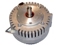
My spreadsheet shows that it's possible to take an ordinary 750 Watt MY1020Z3 and if you use a Sturmey Archer 8-Speed you can reach speeds of 50 mph WITHOUT overheating the motor!!!

For $200 you have a machine that could go 50 mph. (assuming "Road Racer" aerodynamics)


$70
106155.gif


$122
HU2206.jpg
 

Attachments

  • Motor Current Limit Speed Table.gif
    Motor Current Limit Speed Table.gif
    4.6 KB · Views: 5,801
  • Motor Current Limit @ 50 Amps.gif
    Motor Current Limit @ 50 Amps.gif
    13.7 KB · Views: 5,814
Obviously you need the rest of the bike to make it happen.

But do you see the value in this? Even compared to the "Twin" idea this makes sense. If you take a 36 Volt MY1020Z3 and "overvolt" to 48 Volts and then use "Motor Current Limiting" to "suppress" the heating (and probably add a fan too) you are getting tons of power out of a small motor and not producing much heat to do it. It also solves that nasty "hub breakage" issue because the low rpm torque is "suppressed".

I've done dozens of scenarios with the spreadsheets and this one is beginning to rise up as the "most promising".

:arrow: The heat suppression is the "key" here.

By increasing the peak power and reducing the low end torque (and heat) you get an "ideal" motor for the geared bike.

:idea: It should be a kind of intellectual "breakthrough" when people understand this. This is the only way it makes any sense to set up a geared bike. The "Battery Current Limited" standard is really better suited to hub motors that can't shift gears.
 
:arrow: I'm surprised how little feedback I've gotten on this thread.

Now that I understand the theories and formulas and have access to tools (spreadsheets) that can accurately model different scenarios I've been able to get this "eureka" experience about how to properly design the geared bike.

In the past people have been using the "Battery Current Limiting" approach because there was a desire on these electric vehicles with only a fixed gear to try to spread some more torque around to make the motors more "general purpose". While this is fine to do it has as it's drawback the fact that at low rpms you both get current multiplication AND heat multiplication.

The whole point about gears is to "rethink" the way the electric motor is being used. The existing controller setup is all wrong for a geared bike on multiple levels. (excess torque can damage the hub, and excess low rpm torque overheats the motor)

I'm simply surprised that people aren't going "wow"... :shock:

Are people fully comprehending the theory I'm presenting?

Just stare at the charts again... the "better" approach pumps out an extra 250 Watts of peak power... it's the same motor, but just a different controller configuration... (so this is the way to get more power out of a small motor without risking heat related damage)
 

Attachments

  • Motor Current Limit @ 50 Amps.gif
    Motor Current Limit @ 50 Amps.gif
    13.7 KB · Views: 5,753
I think most people understand the concept, which is a good one, but how many people can actually apply this to their bikes? Probably only skilled DIY'ers which are a very small percentage of users.

Hopefully the mass produced products will change, but it will take some time. It's nice to see some of these ebike scooters will finally have some low end torque:

http://e-ride.ca/Electric_Scooters/Motorino_HTh.html

"Motor - brushless high speed with built in Torque converter - Dynatechâ„¢ with CVT transmission"
 
If you need to reduce amps to reduce heat you are at peak power or exceeding it and the limiter would be saving the motor.
Motors do not get HOT if motors are used with in there rated wattage zone.Anything outside of this rated zone heat is due to inefficient motor usage or the wrong motor for its use .Nothing else.
 
EbikeMaui said:
Motors do not get HOT if motors are used within there rated wattage zone. Anything outside of this rated zone heat is due to inefficient motor usage or the wrong motor for its use.

:arrow: This is true.

But the core "issue" that was being examined was that of heating caused by low rpms with the existing "Battery Current Limiting" scheme. Since a geared bike has the opportunity to shift to a lower gear and escape the low rpm heat without losing any power (in fact gaining peak power because you are getting back to the desired rpm for the motor) and you change the controller to "Motor Current Limiting" then it forces the user to shift because the torque that they might accidentally use will no longer be there.

It's "possible" to be in the right gear all the time and if you were to do that you would be fine. But people are "imperfect" and so when you exclude the "bad spots" of the powerband then you guarantee that "perfection" is attained.

:arrow: You can't improve on rider "perfection", but you can "force" perfection on an unskilled rider.

(it's called making something "user friendly" or "idiot proof")

You can ride around now (with the existing controllers) using the wrong gear and overheat your motor if you want. It's actually very tempting to pull a tall gear because the torque is there even though it shouldn't be. On my bike I can usually use any of three gears at any time. The gear that spins the motor the fastest (the lowest gear ratio) and can still pull the speed you want is the "smart" gear to be in, but it can be deceptive as to which gear is "just right". I can sometimes be off by a couple of gears and not know it by feel. By excluding the low end torque you would "know" very easily exactly what gear is "ideal". Only one gear will "feel" right... the gear that is actually correct. There would be less difficulty in keeping it perfectly in the powerband.

:arrow: Why allow what is "always bad" to exist?

There is no logical reason to allow "Battery Current Limiting" for an "adequately" geared bike... no reason at all... can anyone name a reason? (when I say "adequately" I mean that the gearing range needs to be able to cope with either the steepest hill or the fastest top speed which after a lot of calculations I've found the value to be about 300%)


The CVT offers an easy solution to the problem if you can match exactly the rate at which the gearing rises so that the motor is always running at peak power 100% of the time. That's certainly one way to solve it. I'd be curious how they match engine rpms to gearing on that electric scooter... is there some sort of rpm sensor that is plugged into a computer somehow? Is it torque based? Do they then place a controller that is designed to only allow peak power at peak efficiency? (like what I'm suggesting) That's how I'd do it... something like that... there might be more complexity to that than we know... or the actual result is less than advertised...
 
Having a motor capable of providing max torque at regular 8 to 20 mph bicycle speeds WITHOUT overloading the motor would be the best solution.The user of a mulitspeed hub soon relizes that down shifting he will go faster not even knowing high gear is burning extra amps to go slower.A multispeed hub user will have the FUN remembering the old Honda 50 song by the Beach Boys... 2nd gear..Hang on tight! 3rd Gear ......? lol i forgot the last one. but no current limiter is needed if you have a ampmeter or a blinking light and a fuse. or both? Ok
!st gear Hang on tight! .. 2nd Gear Lean Right ! ... 3rd Gear Tt's AllRight !
FASTER__ER ! FARTHER !
Since there not much demand for lightweight lithium bikes it is much more profitable not to design something that works 10 to 20% or better that is light weight when making ther motors desighned FOR use of pedaling at the specs they state witih use of LEAD acid batteries. Anything else is considered a high performance ebike with Advanced technology! LOL :lol: Is It there no $ out there in a investment in up to date design to use for a nice ebike business ? the technology is free if you read.
 
EbikeMaui said:
...no current limiter is needed if you have a ampmeter or a blinking light and a fuse. or both?

True, I've gone through the idea of lights and ammeters, but that's like putting a "band aid" on the problem. The way to REALLY solve the problem of poor gear selection because of lack of "feel" is to make the powerband easier to "feel". Your body can "feel" power... if there is power available then you know you are doing something right. If you are a gear too low then there seems like there is no power because the motor is overrevving. If you were to go a gear above the "ideal" you would find yourself down in the powerband where the "Motor Current Limited" controller will give you no power at all. You would notice:

"Hey there's no power... I need to downshift"

...and in this way you know what is "right" without resorting to measuring it with a meter.

:arrow: Why not? That's the question... "Why Not" exclude what is not doing you any good?

The best reason for having a light would be for the "overrev" situation... that's how it's done in the gasoline world...
 
safe said:
EbikeMaui said:
...no current limiter is needed if you have a ampmeter or a blinking light and a fuse. or both?

True, I've gone through the idea of lights and ammeters, but that's like putting a "band aid" on the problem. The way to REALLY solve the problem of poor gear selection because of lack of "feel" is to make the powerband easier to "feel". Your body can "feel" power... if there is power available then you know you are doing something right. If you are a gear too low then there seems like there is no power because the motor is overrevving. If you were to go a gear above the "ideal" you would find yourself down in the powerband where the "Motor Current Limited" controller will give you no power at all. You would notice:

"Hey there's no power... I need to downshift"

...and in this way you know what is "right" without resorting to measuring it with a meter.

:arrow: Why not? That's the question... "Why Not" exclude what is not doing you any good?

The best reason for having a light would be for the "overrev" situation... that's how it's done in the gasoline world...
Now for using a HIGH TORQUE motor that is as efficient as a hub motor at its best, the Axial flux motors worst efficiency range at 200 to 450 watts would be better % efficiency than a hub motor of the same weight but have 20 times the torque available at even better 90% efficiency to 5 KW. Now this motor and Programable Current limiter , torque limiter and ramp up time ect still weighs the same and costs under $1000. for the more efficient system with limits for legality or any higher use in somthing will never ware out.. with REGEN ! programable of corse.
for half the price in a small volume this single reduction motor and controller would cost the same as a Xlyte motor kit. At 5Kw of power.Not 0.5 Kw rated. for the same price and weight.
With this in mind at $1000. retail price NOW! you can power your ebike or motorcycle by attaching the motor and sprocket to the hub like a currie system.A no brainer for the most reliable and efficient BLDC motor system THAT YOU CAN BUY !!!! TODAY ! a even at the best price per kw ? The best ebikes cost 7 grand ? Money saved to get sporty !
The best deal and use of a "current limiter" :) I could think of.
 

Attachments

  • EtekBrushless.jpg
    EtekBrushless.jpg
    49.9 KB · Views: 5,694
safe
i must of missed it.
what is wrong with the external gears on a regular bike? my bike shop says they are less trouble(non-e) than internal gears.
 
You guys have BOTH missed the point of the thread...

The central issue is not the motor or the gears. Better motors are always more desireable than lower quality motors and the gears I was thinking about were in an internally geared hub, but that wasn't the issue.

:arrow: My point is that if you switch from "Battery Current Limiting" to "Motor Current Limiting" (in the controller) on the geared bike you can extract more power and with less heat.

The "logic" is that geared bikes don't need to "cheat" and get that low rpm torque boost that current multiplication provides, but with that "sin" you now pay a price in extra heat.

Let me AGAIN post those two performance curves of the two CONTROLLER induced results. The motor is the same. Really stare at those red lines because they are the heat produced.

Stare, stare, stare, stare... :shock:

Heat loss is always a "waste" that should be avoided even if the motor is big enough to dissipate it naturally.

More heat translates to wasted battery energy.
More batteries equal higher cost.
Higher cost is always bad.
 

Attachments

  • Motor Current Limit @ 50 Amps.gif
    Motor Current Limit @ 50 Amps.gif
    13.7 KB · Views: 5,649
  • Battery Current Limited @ 40 Amps.gif
    Battery Current Limited @ 40 Amps.gif
    13.4 KB · Views: 5,637
Practical Route to Conversion

The most practical route to convert an existing controller that is using "Battery Current Limiting" to one that uses "Motor Current Limiting" is to do something like "Boost Control". If you add a Hall Effects Sensor to the motor side wire and compare that to the throttle voltage you can create a circuit that knows when to turn down the throttle to keep the motor side current under control. It's a simple circuit to make.

You could in theory have a switch where you could turn the circuit off when you wanted and you could toggle between "Battery Current Limiting" and "Motor Current Limiting" at will.

You can also set the level of "Boost" that you desire.... so the ability to really lean out the bike for long range is also possible.

:arrow: So that's the "practical" side to all of this...
 
so external gears are ok? good.
i have ammeter, so heating is not a problem.
i realize u r designing for "idiots", that is very hard to do, as there is always somebody more stupid than planned :lol:
 
safe said:
Practical Route to Conversion

The most practical route to convert an existing controller that is using "Battery Current Limiting" to one that uses "Motor Current Limiting" is to do something like "Boost Control". If you add a Hall Effects Sensor to the motor side wire and compare that to the throttle voltage you can create a circuit that knows when to turn down the throttle to keep the motor side current under control. It's a simple circuit to make.

You could in theory have a switch where you could turn the circuit off when you wanted and you could toggle between "Battery Current Limiting" and "Motor Current Limiting" at will.

You can also set the level of "Boost" that you desire.... so the ability to really lean out the bike for long range is also possible.

:arrow: So that's the "practical" side to all of this...

Battery current and motor current will basicly be the same thing. You're looking at two ends of a closed system, and one is directly related to the other.

Tou could build a throttle limiter exactly as you say, and it would improve things, but it would also feel strange to ride, and would be prone to speed surges. you would have a situation were the throttle no longer directly effects the speed, but instead the current.

If you reverse the process, and have the motor current regulated by the throttle, I think you would end up with similar results, but a much more linear throttle feel and better speed controll, with a more predictable speed/currant curve. For example, have 10% throttle=5amps, and a non linear curve up to 100% throttle=20amps.
 
Drunkskunk said:
You could build a throttle limiter exactly as you say, and it would improve things, but it would also feel strange to ride, and would be prone to speed surges.

:arrow: Definitely!

Have you ever ridden a fast motorcycle? On the fast bikes they have all kinds of top end horsepower up around 10,000 rpms. This idea would produce a bike that felt exactly like a "sport" road racer motorcycle with a "wicked" top end and nothing to speak of down low. It would definitely be a "peaky" bike and this "peaky" behavior acutally means more power and less heat, so it's for good reason to do.

The way it is now people allow themselves to "drift" down into low rpms and the motor does not "punish" you for "bad behavior". On a "peaky" bike if you drop below the powerband the loss of power is so noticeable that you know that you need to downshift. This is EXACTLY the kind of behavior that you want to force on the rider.

No laziness is encouraged with such a system... it's either "perfect" or you get no power. That's called "providing an incentive" to force the lazy ass to shift! :lol:

No soup for you! :wink:

(the "race inspired" bike is always more demanding than the "cruiser style" bikes. You just don't compare "sport bikes" to "cruisers")
 
I've never rode one of those bikes, but I've driven a few of the old street racer cars with unreasonably high power bands. no power at 4000 RPM, then suddenly at 5000 rpm they're trying to shed their tires. Good times! :D

I see what you're getting at. in that case, my sugestion wouldn't work for you so well.

Still, having the throttle limited by the current would cause it to be unpredictable. you might be in the right RPM range, but the motor is loaded down, so the throttle would feel unresponsive. and 30 seconds later, at the same speed, the motor is nolonger so loaded down, so the throttle becomes sensitive again. it would be hard to controll the bike's speed. Something like trying to steer with Bungi cords.

What about having the current limiter track the RPMs off the hall sensors? Low motor RPMs could have more limiting, and it could ramp up as the RPMs increase. you could even build in a curve so it has that "power band" feel were it only gets full amps in a narrow RPM range.
 
Drunkskunk said:
Still, having the throttle limited by the current would cause it to be unpredictable. you might be in the right RPM range, but the motor is loaded down, so the throttle would feel unresponsive. and 30 seconds later, at the same speed, the motor is nolonger so loaded down, so the throttle becomes sensitive again. it would be hard to controll the bike's speed.

If you look at the chart for "Motor Current Limited" control the powerband rises in an absolutely straight line. That's VERY predictable. What we have now is actually rather "vague" in that it's very hard to tell by feel the difference between bogging down the engine in the low rpms (but with high torque levels) verses hitting the powerband just right. I find the current powerband to be "too wide" and that makes it hard to know what gear to be in.

If it was something other than a straight line it might be a worry, but if you've ever seen the powerbands of a race bike it's not all that different. And we are also talking about only 1-2 hp... on the latest 200+ hp motorcycles they are now looking to flatten out the power in order to prevent wheelspin... somehow I doubt wheelspin is going to be a problem with 1-2 hp. :wink:

This is what motorcycle powerbands look like... it's very similiar:
 

Attachments

  • Motor Current Limit @ 50 Amps.gif
    Motor Current Limit @ 50 Amps.gif
    13.7 KB · Views: 4,626
  • motorcycle dyno.gif
    motorcycle dyno.gif
    24.2 KB · Views: 4,842
Based on testing with my current mode throttle, I don't think driveability will be an issue. It behaves quite nicely since the load increases with speed.
 
fechter said:
Based on testing with my current mode throttle, I don't think driveability will be an issue. It behaves quite nicely since the load increases with speed.

:arrow: How is the development going on that?

At some point I'm going to need to actually build a "Boost Control" and the more knowledge I can accumulate the better.
 
I want to try the "improved" design. The present one still has some issues.

For a straight current limiter, it's much easier. I used one on my Zappy that measured the motor current, and it worked fine. A motor current limiter for a brushed motor is straightforward.

The current feedback mode throttle is trickier. I'm still not really happy with the design, since the adjustments are interdependent. I'm sure there's a way to do it, but I want to keep it as simple as possible at the same time.

Testing has been slow due to flat tires, blown throttles, and general busyness.
 
fechter said:
I used one on my Zappy that measured the motor current, and it worked fine. A motor current limiter for a brushed motor is straightforward.

It seems to come down to understanding how a "comparator" works. The "feedback" of a "comparator" is a little funky for people not used to electronics, but if I put my mind to it I'm sure I can get comfortable with it's weirdness.

:arrow: Could you post something about that "super simple" version you did?

Maybe would it be possible for you to explain how the circuit works... getting into the "quirks" that non-Electric Engineers might have trouble with?

I have a feeling that in the end I'm going to have to "hit the books" myself and truly understand what is going on... but a little coaching and encouragement never hurts... 8)
 
It is best to have a current limiter start to cut in when your morors efficiency starts to drop and the limiter keeps the motor or controller from over heating. When you know you are slowing down it is time to shift down just to get a better speed if nothing else. You can see how a 27 amp limiter works perfectly in this video.So do the gears and complete sysyem with a 5 lb motor.In a stall mode (nearly stopped} the controller only feeds the amps and voltage the motor can use most efficiently at a high load and low RPM.. With coreless rotors,stators or weak magnets or stator fields the low end torque is almost non exsistant in the same size motor yet the power wasted is way up there..
Notice that when the RPM start gaining the controller slips in some more juice (watts) when it is overcoming its max efficient load efficiency starts getting even better as the RPM is boosted when it would be meaningful.
http://video.google.com/videoplay?docid=-1501457501981349249&q=ecyclemaui
 
Here's about the easiest one that will work nice. This one is still setup for limiting the input current, but should work with amost any controller.

I'll see if I can draw a different one that will limit the output current (motor current), but it will only work with brushed motors. A brushless version that limits motor current is possible, but I'm not sure how to measure the current.

When the current is near zero, the voltage across the shunt is also zero.

The lower limit pot is adjusted so the amplifier output is normally high. The diode on the output prevents the amp from driving the throttle line up.

When the voltage drop across the shunt increases enough, the comparator threshold will be crossed, driving the output of the amp low. The diode conducts, pulling the throttle signal low. The resistor in series with the throttle signal limits the current on the output of the throttle hall to prevent overcurrent.

The .01 capacitor between the output and negative input will act like an integrator and limit the speed of the output change (slew rate). This may be unnecessary with some controllers. This acts as a loop filter to prevent oscillation in the feedback circuit.

The inputs to the amplifier are fed by voltage dividers to keep the input voltages between the supply rails. The input range for most op amps is limited to the supply rails, or not quite to the rails, so the divider keeps the inputs happy. The dividers also allow for adjustment.

The LED is handy for making adjustments and letting you know the thing is alive.
 

Attachments

  • Current Limiter 6.jpg
    Current Limiter 6.jpg
    32.1 KB · Views: 4,563
Analysis

:arrow: Sector 1: The Shunt in this version is connected to the "Battery Side" but for my intentions I would do the same thing, but use the "Motor Side" wires instead. Is this correct? (for brushed motors it seems so)

:arrow: Sector 2: If I'm understanding this correctly you have two "trim" pots for the upper and lower range so that the final third pot will be adjusting properly within a range that is useful. That seems like a lot of pots to get the job done. Do you really need three? (a good question)

:arrow: Sector 3: This looks like where you placed the capacitors that help to dampen the throttle current to the controller. Is this a "must" or just something that makes it better? Would it be possible to not use capacitors here? (you seem to say "maybe")


:idea: What if you built the circuit in "steps"?

First you install a shunt and measure exactly how much voltage you get out of it. Then since you now know exactly what voltage you have you then get a pot that fits it "good enough". Then you attach the comparator and the diode and see if it works without needing capacitors. If this all works "okay" then you stop, otherwise you continue to add features as needed.

The more minimal the better... I'm still not completely comprehending this circuit... :?
 

Attachments

  • current_limiter_6_389-analysis.gif
    current_limiter_6_389-analysis.gif
    44.5 KB · Views: 4,549
Back
Top