geosped
100 W
- Joined
- Mar 18, 2015
- Messages
- 258
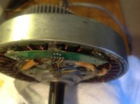
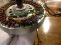
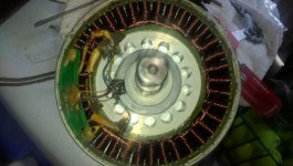
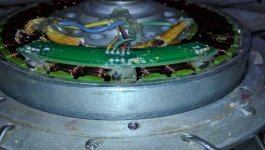
I recently burned out the hall sensors on my BMC Gear Hub and would like to rebuild it but have run into some snags and have not found a good DIY.
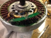
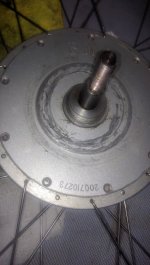
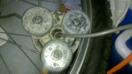
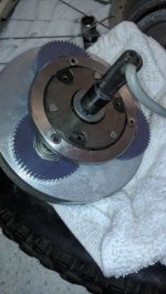
1) Can anyone identify what version this is? As you can see they have the white gears.
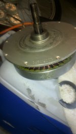
2) I can take the can off but unable to figure out how to disassemble this further so that I can get to the hall sensors. Anyone have a clue? If I had to guess I'd have to drill out what looks like rivets?
3) From what I understand there are steel gears I can purchase for better durability. Would these be recommended for off road use?
4)Who offers rebuild services? And how much would I expect to pay? I will reach out to Leyn and @ Ebike CA anyone else?
For those that are wondering. I use this for off road. I run 10Ah 48v pack pushing around 1300-1700w for short burst of about 10-15 seconds during climbs while riding. I'm 250 and I'd say it's a bit more that this setup can handle lol. This is the setup I want to run and it's been pretty durable. I just want to rebuild this and keep going.
Help is greatly appreciated!
Regards
-G

1) Can anyone identify what version this is? As you can see they have the white gears.
2) I can take the can off but unable to figure out how to disassemble this further so that I can get to the hall sensors. Anyone have a clue? If I had to guess I'd have to drill out what looks like rivets?
3) From what I understand there are steel gears I can purchase for better durability. Would these be recommended for off road use?
4)Who offers rebuild services? And how much would I expect to pay? I will reach out to Leyn and @ Ebike CA anyone else?
For those that are wondering. I use this for off road. I run 10Ah 48v pack pushing around 1300-1700w for short burst of about 10-15 seconds during climbs while riding. I'm 250 and I'd say it's a bit more that this setup can handle lol. This is the setup I want to run and it's been pretty durable. I just want to rebuild this and keep going.
Help is greatly appreciated!
Regards
-G

")