Xaomi controller circuit

Greengear

1 mW
Joined
Jun 1, 2018
Messages
12
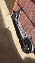
I found an abandoned, vandalized scooter in the gutter no battery or handlebars. It appears to be very new technology compared to other ebikes.
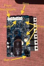
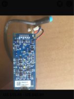
I connected a 36v power source to the controller. The wire harness that leads up to the throttle and on off panel has 4 wires, one of which is pack voltage. In previous troubleshooting of other e bikes I have found that the handlebar mounted screen sometimes has a 5 v regulator built in. The throttle frequently plugs into the handle bar screen, the screen into the controller. My question is how can I determine if the controller is waiting for a simple 5v throttle and or key on signal or if the controller is waiting for some sort of high speed network connection (can).
I could borrow an identical scooter to test the signals when the scooter is enabled and disabled.
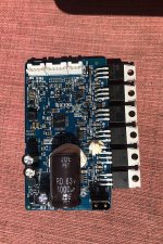
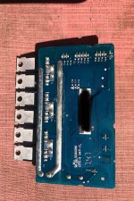
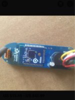
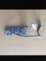
Image of controller, vandalized frame below. My goal is to use the rear wheel and controller or to find a replacement controller that can run a very small hub motor in sensorless mode.
 
Looks lke I cant post pics yet as a new user. I will post pics when that feature is unlocked.
 
You should be able to post pictures. Go to attachments, Add File, and place in-line. Helps if the pictures are resized smaller but the forum software is supposed to do that automatically (sometimes).

The pack voltage going to the display is often switched there and sent back to the controller on another wire. Just by completing this circuit, it might turn on. The display also sends serial data to the controller to set the mode or parameters. Default startup mode for the controller may or may not run the motor. The throttle typically goes straight to the controller as an analog signal (1v-4v).

If you have a working one, measure the lines going to the display when turned on and when turned off to see if a line is getting pack voltage only when on. It is also possible to monitor the data on the lines using a laptop and something like Hyperterminal or another serial communication software. If data is required to make it run, it may be possible to program an Arduino to emulate the display.
 
Pictures below. The controller looks more modern than I am accustomed to seeing.
 

Attachments

  • D61C5917-E739-4247-8FDD-40CB43D699FB.jpeg
    D61C5917-E739-4247-8FDD-40CB43D699FB.jpeg
    189.4 KB · Views: 1,206
  • EF190722-DF16-4E9A-99AD-0A23C59604C1.jpeg
    EF190722-DF16-4E9A-99AD-0A23C59604C1.jpeg
    219.5 KB · Views: 1,206
  • 64C0B5F6-6AED-4CA1-8567-385E52ED135B.jpeg
    64C0B5F6-6AED-4CA1-8567-385E52ED135B.jpeg
    223.2 KB · Views: 1,205
  • EA544481-14C4-49A3-904F-777E2D937448.jpeg
    EA544481-14C4-49A3-904F-777E2D937448.jpeg
    158.8 KB · Views: 1,204
Great pictures.

Only 4 wires to the handlebars? I suspect one ground, one 5v, but to send data usually takes 2 pins. If you measured the pins on a working one you could see which ones are ground and 5v and see if one acts like a throttle signal (1-4v). Possibly the throttle is done by serial data, but I have never seen that before.
 
The 4 wire set definitely includes pack voltage so with only two remaining pins it is hard to imagine how the headlight, throttle and brake switch opperate.
The pictures are from an alibaba page selling the top side board
Link to ad
https://m.aliexpress.com/item/32839123705.html?trace=storeDetail2msiteDetail&spm=2114.12010612.0.0.88e042c7Cj36rh
 

Attachments

  • 01DDC439-DBAA-46AE-88F8-EDD42B36E007.jpeg
    01DDC439-DBAA-46AE-88F8-EDD42B36E007.jpeg
    103.6 KB · Views: 1,184
  • 248217C9-8AA0-4C4C-BC46-68477B029FC7.jpeg
    248217C9-8AA0-4C4C-BC46-68477B029FC7.jpeg
    118.7 KB · Views: 1,184
  • C92B63CA-2697-4E48-9493-1EC41DFB9163.jpeg
    C92B63CA-2697-4E48-9493-1EC41DFB9163.jpeg
    94.6 KB · Views: 1,184
Well, then most likely it sends all the signals digitally to the controller. Does the throttle go to that board?

Getting that board seems like it would solve your problem. Duplicating it would take quite a bit of work.
 
As a personal challenge more than nessesity I want to try creating an arduino software to communicate with this controller. I have a friend who owns a working complete scooter. I can connect to intercept data signal.
What device could forum members recomend to record serial data stream. Reverse engineering handlebar controls is slowly becomng essential to ebike repair. The handlebar control is often broken and also frequently unavailable for older models. The only flaw in this idea as a repair strategy is you need a working example to fix the broken bike.
 
Greengear said:
What device could forum members recomend to record serial data stream. R

Desktop or laptop computer, and terminal programs like Realterm, Docklight, etc. Might also need a USB-serial adapter if the computer doesn't have a serial port that supports either 3.3v or 5v serial data lines (TTL) rather than the +v/-v RS232 type of serial data lines (otherwise you may damage the device you're trying to read/write to, or the computer, or both).

If it helps, you can search the forum for threads with "serial" or "protocol" in them; there are some attempts to decode what various things send.

THere's also info on that type of thing in Casainho/Stancecoke/etc's threads about making new firmware for some LCDs and controllers.
 
Greengear said:
As a personal challenge more than nessesity I want to try creating an arduino software to communicate with this controller. I have a friend who owns a working complete scooter. I can connect to intercept data signal.
What device could forum members recomend to record serial data stream.

Sounds like fun. If I was doing it I'd try my new Rigol oscilloscope to see what the signal looked like. Possibly it could even decode it as it supposedly can decode spi/i2c/serial bit streams. Haven't tried it yet.

If I did not have a scope, I'd try a serial term, but I doubt this will really work as there is no reason to send legible ascii between devices like this. So it's probably some sort of binary message format.

If the serial term did not work out, I think next I would try programming another mcu to sample the line really frequently and log it somehow for analysis later. A DIY logic analyzer for just one channel. Or just use it as an excuse to actually buy a logic analyzer. ;)
 
-dg said:
If I did not have a scope, I'd try a serial term, but I doubt this will really work as there is no reason to send legible ascii between devices like this. So it's probably some sort of binary message format.
Since terminal programs like Realterm can display the received data in pretty much any format from binary to ascii to hex, etc, and you can change the stop bits, parity, etc., as well as port speed, it's still possible to use one to figure out what's being sent. Might take a fair bit of experimentation, capturing to different files and sorting thru the data for patterns, but possbile.
 
Great advice everyone. I will wipe the dust off my usb osciliscope and capture the output as a first step and post pics here.
 
I tried playing around with a damaged controller from a BBSHD just to see if I can capture the data. With my oscilloscope and the chart from the website, it indicates 1200 baud. Next I'll see if I can capture it using the USB programming cable. There is a thread where someone is trying to decipher the code for the BBSHD here:
https://endless-sphere.com/forums/viewtopic.php?f=2&t=94850&p=1398699#p1398699

The process would be pretty much the same.
 
I will look at the post for more info.
I was able to capture a decent image of the communication. The four wires are red black green and yellow. Going on the assumption the green and yellow were comm wires was wrong. After more experimentaion it seems that there is 5v, ground, pack voltage and a single com wire. With the scope on ground and yellow I got this.
2.jpg
 
I guess I put the cursor in the wrong place to measure shortest pulse. Looking at the divisions it seems like 10us.

I will order an rs 232 serial to usb adapter as I cant seem to find the old one I had lying around.
 
That’s not the flavor you want. You want one that goes from USB to TTL-232. 0-5v logic signals like a Bafang or Infineon programming cable.
 
Is this one appropriate.
https://www.amazon.com/USB-TTL-232-converter-serial/dp/B01CNW061U/ref=mp_s_a_1_6?ie=UTF8&qid=1534116404&sr=8-6&pi=AC_SX236_SY340_QL65&keywords=usb+to+ttl+232

I believe I have an infineon cable purchased about 5 yrs ago but it may be like looking for a needle in a haystack.

The bafang cable might be a good option if all else fails because they are readily available.
 
Back
Top