New controller issues..... where to go from here

GregO

1 mW
Joined
Jun 3, 2018
Messages
19
Any help would be appreciated,,, new ebike conversion. I bought the kit from china. rear hub 48V 500W with disc brakes.

I could use some input from a knowledgeable source

I have everything wired up. Very good charge on my battery. Power going to throttle light "indicator lights", brakes contacts are closed and in the ready position... ( I also disconnected them to rule them out), PAS on the pedal and a mere 2mm from the magnets... all connections are triple checked. I turn on the battery... as I mentioned the lights light up on the handlebar... but i get no power to the wheel as I twist the throttle. I unplug the motor connection and put a voltmeter on the controller motor output, and the volts stay at a steady 4.5V when I twist the throttle.

Any suggestions?
 
Would it be Kosher for me to directly hook up the battery to the motor for a second? I dont want to fry anything though
 
No. That would not work unless it's a brushed motor. If it's a brushless motor, you could fry the battery, You should disclose your system, brushed motor or brushless motor, and describe the motor cable and its connectors to get better assistance.
 
And how many wires your brakes have... Sometimes they use Hall sensor cutoffs with three wires that need to be hooked up for the system to run. Also some have an ignition wire that needs to be hooked up...
 
And if you have a brushed motor (2 wires) you can simply hook it up for a second, but make sure it's rotating the right way or the pedals start flying around. But def not if it's a brushless motor.
 
The leads from the breaks are 2 lines each. I iwired it as if its one large circuit, and any interuption, either from the left or the right break would break the loop stopping the motor.

I also unplugged that to test it without the break disconnect and still nothing.

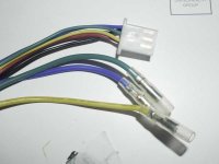
The wiring from the motor connector are red and black at the top (power) , and just below on the connector is Yellow, Green and Blue,

It does not mention that it is brushless in the description... Here was the Description. Please let me know if there is any more info needed Thanks!

26" Rear Wheel 48V 1000W Electric Battery Powered Bicycle Motor Conversion L3T1 See original listing
26-034-Rear-Wheel-48V-1000W-Electric-Battery-Powered-Bicycle-Motor-Conversion-L3T1
Item Ended
Condition:New
Ended: Jun 18, 2018 , 10:38PM
Price: US $215.74
Shipping: FREE Standard Shipping
Item location:Memphis, Tennessee, United States
Seller:
homegarden2012 (411981 )
 
you have checked all the plugs carefully, but nevertheless, the single most likely problem is a bad or loose plug not quite connected right. If you have the square white plugs, they are notorious for having a contact back out as you plug them in.

I'm a bit confused by your motor plug, but it must be a sensorless motor. b g and y wires are the motor power. Not sure what the black and red do, but they might be a thermal switch to cut off the motor if it overheats.

Its possible that you have simply received a controller that does not work, but try one last test before giving up. try rolling the bike forward a few inches as you apply the throttle, and see if you can get it to run that way.
 
Hey dogman... yeah I did each thing already... coming from the motor...the black and red connectors are for power and the colored are for motor phases?? ... I imagine low, med and high speed from the throttle.

This is incredible frustrating... but I have put my voltmeter on and the power is 51V from the battery... and I know it is in through the controller because of the lights (battery indicator) next to the twist throttle I may just hook the battery directly to the motor to see if it isnt the motor.
But will monitor this thread more for a while to see if someone can give me a good answer Im ready to try even more. I dont want to fry anything... so I will take my time and learn from you pros firstr
I am noticing online that there alot of different controllers.. some with Hi nd lo brakes, alarms, regenerative braking... yada yada...mine seems simple... yet confusing if I cant get it to run. eSeveral people told me that all you need to make the motor basically run is contact to and from the motor, battery and throttle... and all the rest is candy such as PAS, Brake cut-out... definitely needed but I need to start properly ruling out one switch or component after another to get this right.
 
Looks like you bought an ebay kit from a big China seller of everything. Listing is expired. Can you still link it? Can you post pictures of your motor and throttle connectors?.

There was only one brake connector? Your description says you wired the levers in parallel. That wouldn't work if the bike was running.

If it were me, I'd want to check the throttle voltages. Does it have a start button with LED's to show power level or is it simple throttle only? No one here can tell you what to check unless they know what you have. Pics of everything.

Like this is a sensored motor connection coming out of a controller. You only got the blue/yellow/green and two red/black?

P1060194.JPG
 
If it's a three phase brushless motor, the resistance of the windings is under an ohm. You know ohms law says 51volts/.1ohm is 510 amps. Kaboom to your battery.

On the other hand, red/black could be the power for a brushed motor, and the three other wires could be a speed sensor, but then the red/black will be big heavy wires and y/g/b will be relatively thin,
 
Thanks docw009 Your picture there is spot on!

Heres a better link descriptor... I have pics of course but havent put any on this forum before But I will learn to and do it now... BTW i did test the continuits on the brakes and they close the loop when the brakes are depressed. Not sure why I had only one brake disconnect connection... but until I get the power to the wheel resolved... I am hooking up only one for now... with power on and a voltmeter... the red green and black line coming out of the controller shows 5.0 unnamed-2.jpg
 
Usually red/black/green is throttle or PAS. Some kits you can reverse the plugs for the two of them, so that's a maybe. But if you're sure that there's the right voltage going to the controller, and the phase and Hall wires are right, and there's voltage at the throttle.. then you're into maybe bad Hall sensors from the factory in the motor, which is what was wrong with a guys kit I just fixed, after wasting a bunch of time on checking the normal stuff.

Side note, are you sure there's not an ignition wire in there somewhere, a single red that isn't hooked up yet?
 
Hey Voltron... Yeah I am sure there is not a single red wire left... I have an extra red/black for a battery meter or a headlight perhaps.. but no single red.

I am starting to fear that the motor is bogus. I have no idea how to test it... and have no plans on doing that... but after I ruled out all possibilities this evening and Sunday... The motor will have to go back starting Monday. I am wondering if there are any tests without buying a Chinese Ebike tester I saw a few people using on Youtube... but no I bought this new and the onus is on the seller. I bought it off ebay and return freight on this is the sellers responsibility. I am just wanting this one to work. Not to come of as racially insensitive here but the kings english is not too good on any emails.

I am wondering if anyone can tell me how to test the current coming from the controller to the motor... which leads should show what... and throttle position. Going crazy over here.
 
Two test to do next are testing the throttle and the Halls. They both work the same way.. If you probe with your meter with the system on, you should get about 4.8v or so on the red and black of the two plugs. Between the black and the other wires should have no voltage. As you turn the throttle it should start going up to about 4.2v.

The Halls are the same way.. If you meter between black and each color one by one, and spin the wheel, it should blip the voltage intermittently up as magnets start passing the sensors.

That's effectively what the Chinese tester does, except running off a battery so the test can be done without a voltmeter and without the parts connected together.
 
I alphabetized all my leads in this pic
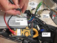
A are the 3 lines that go to the motor i think are the Phase
B is from the controller to the motor... it has Red Black at top and BGY
C, D and E all run to the twist throttle
F is the Battery
G is the Hand Brake disconnect
H is the PAS
I is just a Blk and Red lead that is extra for a battery monitor or head light


You are saying to run my voltmeter to The Throttle C, D , and E.... but do you consider the Halls as BOTH the PAS and Hand Brake disconnects?

I appreciate the help
 
Sorry if it was confusing.. The throttle (which has a Hall sensor in it) and the Hall sensors in the motor both get tested roughly the same way. I was wondering if you maybe had Hall sensing in your brakes too, but you don't.
 
GregO said:
The leads from the breaks are 2 lines each. I iwired it as if its one large circuit, and any interuption, either from the left or the right break would break the loop stopping the motor.
Rather than a series connection like that (which won't work), you should parallel the brake wires. Doesn't matter which way, as long as one wire from the left brake lever is connected to one wire from the right brake lever, and the other wire from each brake is connected together. Then each of those pairs goes to one of the controller's brake input wires (doesn't matter which).


The wiring from the motor connector are red and black at the top (power) , and just below on the connector is Yellow, Green and Blue,
Those are probably just the hall sensor wires. (if they are all thin) (they just tell the controller what position in rotation the motor is at, and which direction it's going).

You should also have three thick wires from the motor to the controller (phase wires). If not, then that's the problem; without them there's no power going to the motor itself.

it's unlikely that simply matching them by color will make the motor work, even though it is a "kit". You may have to go to the thread for Determining The Wiring for A Brushless Motor and do the sequence of tests there, after you've gotten the system to do *something* (even if it doesn't spin right).


If three of teh five wires are thick, and two are thin, then it's probably a sensorless motor, and would require a sensorless controller to run it; the three thick wires would be for the motor power. The other two thin wires would then most likely be a wheel speed sensor.


GregO said:
I alphabetized all my leads in this pic
There's no pic attached....


http://ebikes.ca has a tab for Learn, and then Troubleshooting, which has a number of good testing guides that may help you, too.
 
Ok, now I understand your motor wires, they are normal. Big bgy wires are motor power, they will switch on and off one by one to make the wheel turn. This timing is controlled by the little wires, which is where I betcha your bad contact is.

Here is what I would do. It appears your battery connection is good, and the controller is powering up, because you have 5v on the red wire to the throttle.

Connect the power to the controller, and with all wires to the motor disconnected, look for 5v on the thin black and red wires to the motor. If you dont have 5v there, that is your problem. If you don't have 5v on the skinny red wire to the motor, your controller is not functioning right.

Next, disconnect the battery from the controller. While the wheel is completely unplugged, spin the wheel and feel any resistance. There should be some, but not much. Now plug in the large motor wires, and spin the wheel again. If you feel a large resistance after you plug it in, then you have a blown controller.

If it passes this, then power up, plug in the motor, but not the brakes or the throttle, lift the wheel off the ground, and do something to connect the red wire on the throttle plug, to the third, non black wire on the throttle plug. On the controller side of the plug I mean, you are simulating full throttle when you connect red to the third wire. If its just your throttle, when you short those two wires it will make the wheel start spinning.


Those are the easy tests. You can test everything on the kit easier if you get a motor/controller/ throttle tester. The chances the problem is actually in the motor is unbelievably small. But the controller can have a component in it fail on the second time it got powered up. Rare still, but not rare as a motor fails.


You may have just recieved a bad controller or bad throttle in the kit. But its still about 99.5% likely you merely have one of those little contacts backing out of the plug housing when you plug it in, and I betcha its on the throttle or the skinny wires to the wheel. Plug in, and look hard down the holes on the backside of the plug, seeing if all the contacts still look all the way in, and tug on wires to see if any come back out.


if you took any of those plug housings completely off, then you did it, you mixed up the wiring. Customers do it all the time, and they never tell the troubleshooter they did stuff to the kit. I doubt you did that, but I've seen it hundreds of times working CS for a kit company.
 
More Pics would help, but .... I think you've shown you have a typical brushless motor with three heavy pahse wires with bullet connectors and a rectangular plug with 5 wires for Hall sensors. Make sure that the wire colors on both sides of that plastic plug match up. Make sure; like Dan says, that the connectors are making contact. Make sure the bullets actually touch.

I cannot tell what you did with the brake connector, but don't plug it in for testing.

If that is indeed your throtle plug, and you will know if the throttle fits it, the green wire is the signal. Tyr to measure it with the thruttle plugged in. It will start at about .80 volt and increase to 4.0-4.2V when the throttle is rotated.


unknown copy.jpg
 
I have a feeling that one is PAS... usually, but of course not always, the smaller black plug with the red black green is throttle, and the Molex big white one is PAS.
 
dogman dan said:
and do something to connect the red wire on the throttle plug, to the third, non black wire on the throttle plug. On the controller side of the plug I mean, you are simulating full throttle when you connect red to the third wire. If its just your throttle, when you short those two wires it will make the wheel start spinning.
Just a note: for certain controllers that have a throttle-voltage-high protect, where if they go above a certain voltage (4v? 4.5v? depends on the controller) then the controller shutsdown to prevent a stuck-on-full-throttle situation due to a short in the wiring.

For those contorllers, connecting the 5v directly to the throttle signal in wire on the controller won't do anything. You'd have to use a voltage divider or a potentiometer.

So if nothign happens when you try this test, it doesn't necessarily mean the controller doesnt' work or that your throttle isn't the problem--it could just mean that your controller has this protection.


However, one thing that isn't protected against in even those controllers is a break in the ground wire--meaning, if you connect the throttle up normally, then disconnect the ground (uusally black) wire only, it may start the motor going, depending on how high the voltage floats to without a ground wire.
 
Could the issue be a bad BMS in the battery pack? I have read that they can blow and still have voltage on the discharge leads but won't deliver any current.
 
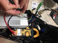
Hey Voltron... I HOPE I found my problem... this is my motor cable, bike is ON and this is coming out of the controller it has a red/ black at the bottom. I used my volt meter and put one on black and the other on:
BLU 5V
Green 0 V (problem child?)
Yellow 5V
 

Attachments

  • IMG_0721.pdf
    1.6 MB · Views: 24
Technically, that is the Hall sensor plug to your motor, one of the two important cables to your motor.Your situation could be normal.

If you have the wheel powered up, turn it slowly and a working wheel will flip the blue, green, and yellow wires in your plug between 0 and 5 volts as the wheel rotates. That's how the controller knows the wheel position. If one wire is stuck at 0 or 5 volts when you turn it, then you do have a problem. The plug, of course, needs to be connected.

Good luck testing!
 
Back
Top