How do I set up a relay for BMS to turn positive pack voltage off

John in CR

100 TW
Joined
May 19, 2008
Messages
14,954
Location
Paradise
To me it's still unbelievable that main current runs through BMS's. I just want the BMS to turn the controller off. There's gotta be an easy cheap reliable way to have the cutoff at the negative end of the BMS switch a relay off that goes to my low current key switch at + pack voltage. My controllers limit current just fine, so I have no need for the BMS to protect my packs from over-current. While I'm my own bikes' BMS's I can't in good conscience sell a full bike or battery pack without one and I want to make those BMS's more reliable by not sending full current through them, just provide cell level LVC and top balance during charging. I will run charge current through the BMS to protect the pack from charger failure.
 
Depends on how the gate drive works in the BMS, but if it can source enough current, you can simply disconnect the gate on the FETs, then run the gate driver output to the positive of the relay coil, with the negative of the relay coil to battery negative.

What voltage the coil needs to be depends on the voltage out of the gate driver.

If the gate driver cannot source much current, you can have it drive an NPN transistor instead, and put the transistor in the negative side of teh coil (between the coil and ground), and run the positive of the coil to battery positive (using a relay with a coil voltage the same as your pack voltage), or run the positive to the power supply of teh gate driver (with a coil voltage the same as whatever that is, and assuming that power suply can supply the coil current).

Some info on driving relays; it's pretty simple
https://www.google.com/search?q=driving+a+relay&ie=utf-8&oe=utf-8


Then use the relay contacts to break the connection of the keyswitch wire to the battery positive. The contacts must be rated for DC, and a minimum of whatever the fully-charged pack voltage is. They must also be rated for the maximum current the keyswitch line sees, so if you're powering a DC-DC from that as well, make sure whatever it's peak current is is taken into account.

NC contacts will be normally-closed, meaning when the relay coil is NOT powered, the battery will stay connected to the keyswitch.

NO contacts will be normally-open, meaning the battery will be connected from the keyswitch only whenever the relay coil IS powered. (and disconnected whenever the relay coil is NOT powered).

So it depends on which way you design the coil drive circuit which contact set ot use, but I'd recommend using the NO set, so that when power fails at the battery for whatever reason, it disconnects the keyswitch from it, making it unable to turn on the bike under that condition.


FWIW, this setup is going to disconnect the keyswitch power under *any* condition that triggers the BMS shutdown, including overcurrent if the BMS monitors that. If you don't want that to happen, you'd need to defeat the overcurrent protection of the BMS (like by replacing the shunt in it with a big fat wire).
 
Thanks AW,

Regarding your last paragraph, my whole objective is to bypass the BMS for the controller mains, so only low current flows thru the BMS. Then I can use a cheaper lower current rating BMS. Now that I think about it, maybe just have a BMS shutdown trigger a buzzer and a light getting power from the DC/DC converter. Then I can just use a cheap 12V relay and a BMS cutoff can't shut the bike down at an inopportune time like in the middle of an intersection, or during a acceleration merging into traffic, or simply a mile from home, enabling me to use a more conservative cell level LVC on the BMS.
 
You can power most controllers with 12V, So you can connect the DC to DC Converter to the BMS and you're good to go.
 
I'm sure there's a way to make it set off an alarm when it trips. The tricky part is to design it so it doesn't add standby drain.
 
eee291 said:
You can power most controllers with 12V, So you can connect the DC to DC Converter to the BMS and you're good to go.

Great idea if it works. If not, then I could modify the stepdown to take 12V, which I think is pretty simple depending on type. I'm not sure I like the idea of lights and power shutting down with a BMS trip, especially at night. :shock:
 
fechter said:
I'm sure there's a way to make it set off an alarm when it trips. The tricky part is to design it so it doesn't add standby drain.

If I go audible and light alarms on a BMS trip, they'd be fed 12V by my DC/DC converter that gets power only when the key switch is on. Wouldn't that prevent any standby drain, or are you talking about causing the BMS to have more standby drain?
 
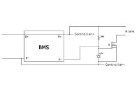
So here's a diagram of a possible solution.

BMS alarm interface 1.jpg

Most BMS units have the B+ and P+ directly connected internally. Your controller can go straight to the B+ and B- points so it won't get interrupted by the BMS when it trips.

The P- connection is normally connected to B- by the discharge FETs. When the pack trips, P- will go open. The FET Q is normally turned off when the BMS is happy. When it trips, the resistor will pull up the gate and turn on the FET and set off the alarm. During normal conditions, the resistor is putting a small drain on the pack. 10M is big enough to keep this minimal. Alarm output is full pack voltage.

An alternative is to power the circuit from your dc-dc converter instead of the pack. This would eliminate any standby drain and allow your alarm output to be 12v instead of full pack voltage. In order for this to work, your dc-dc needs to have the negative output tied to B-. Some will already be like this. If you can do it this way, the resistor should be a lower value, like 100K.
 
The BMS I have uses an external shunt for total current measurement to/from the battery pack (on the negative), individual cell voltage measurements, as well as 2 relay control outputs for charging, and discharging. Amongst other features (like an audible alarm).

So for discharging, when it detects the conditions' thresholds you've set, like over current, under voltage, it will de-energize the discharge control output, and whatever you have connected to it, like an NO-relay, will open.

So you could have this discharge relay setup to turn on/off the controller, instead of cutting power to the controller.

That's what you want, right?

If you only need up to a 16S, you can get the BMS16, it's around USD$120.

https://www.aliexpress.com/af/BMS16.html?SearchText=BMS16&d=y&blanktest=0&initiative_id=SB_20180715144446&origin=n&catId=0&isViewCP=y&jump=afs
 
Back
Top