
I use this pretty generic hall effect thumb throttle with my BBS02. Right now my BBS02 keep reporting error 04 anytime the throttle is plugged in (unable to zero the throttle).
I ripped it apart to the PCB inside and checked all the wiring and it looks fine. I get +5v on the red +5v wire, but the blue signal wire seems to be stuck at +2.3v as if the sensor was always at 0 gauss. When I move the throttle lever the voltage on the signal wire doesn't fluctuate, but if I take a strong neodymium magnet and put it next to the hall effect sensor it will drop to 0v and up to +5v depending on the polarity of the magnet.
The magnet in the throttle lever still seems to be polarized, just the sensor isn't detecting the polarity as if it isn't sensitive enough. Is it possible the hall effect sensor itself is bad even if it works with a strong neodymium magnet?
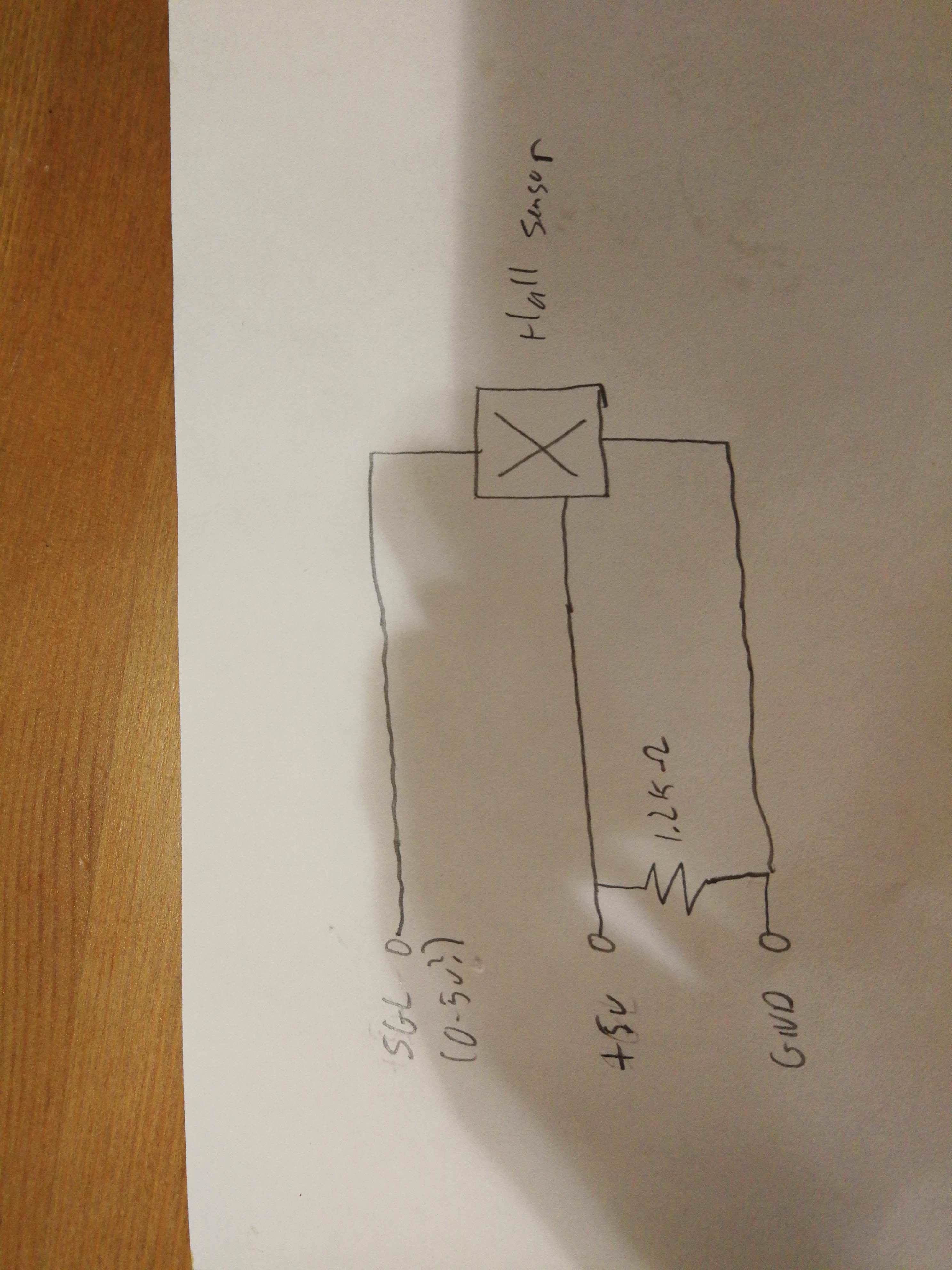
I attached a picture of the hall effect PCB schematic that I sketched out. I have no idea what the 1.2k resistor is doing in this case but it is there on the PCB.
I ripped it apart to the PCB inside and checked all the wiring and it looks fine. I get +5v on the red +5v wire, but the blue signal wire seems to be stuck at +2.3v as if the sensor was always at 0 gauss. When I move the throttle lever the voltage on the signal wire doesn't fluctuate, but if I take a strong neodymium magnet and put it next to the hall effect sensor it will drop to 0v and up to +5v depending on the polarity of the magnet.
The magnet in the throttle lever still seems to be polarized, just the sensor isn't detecting the polarity as if it isn't sensitive enough. Is it possible the hall effect sensor itself is bad even if it works with a strong neodymium magnet?
I attached a picture of the hall effect PCB schematic that I sketched out. I have no idea what the 1.2k resistor is doing in this case but it is there on the PCB.
