I'm glad you've got it working as you need it to.
The below reply is just for reference for future readers:
David Gri said:
I guess it is one part of the issue, the relay need 50mW to work.
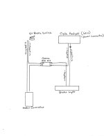
But when I test without the relay, so plugged like that :
then the CA screen was brighter while braking.
I checked the wiring, that was the same than in the picture (I'm not electrician, but electro-technician )
If you have regen braking, then the screen would be brighter as the motor slightly increases teh voltage on the CA until the motor slows enough to not be able to increase the voltage.
If you either don't have regen, or the brightness change happens even at a stop just engaging the lever, I don't know why it would happen with only the standard brake switch connection to the CA brake signal and ground wires.
One possible case that using just the brake lever switch on the CA input *could* cause a brightening of the screen, is if it is accidentally connected across the 5v and ground instead of the ebrake input and ground, as it would short out the 5v, causing the screen to brighten momentarily form the higher current draw, but the CA would blank the screen during brake lever pull, and reboot after you let go.

So that's probably not what is happening.
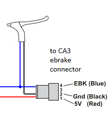
I removed everything, then I plugged an on/off switch between the EBK and Gnd of the cycle analyst, and cycle analyst is working fine like that.
Ah. Then that's normal.
I did it before with only the braking relay (that was working*, and also plugged between the EBK and Gnd) but the cycle analyst didn't recognised it, so I thought the cycle analyst was dead.
* when it is open, the impedance is 0 Ohm, when it is close, the impedance is 13K Ohm
If by "when it is open" you mean when the relay is off, (brake lever not pulled), then getting zero ohms on that means it's the opposite kind of relay you need, or the wrong set of contacts is being used. To get 0 ohms when relay is off, it would have to be the NC (normally closed) set of contacts, but what you need to use for your system is the NO (Normally Open) set of contacts.
The NC relay is shorted (zero ohms) when off, and high or infinite resistance when on.
The NO relay is high / infinite wehn off, and zero when on. (this is what you want).
Alternately, if what you actualy saw on the meter screen was "OL", that means "overload" or "overlimit", and means the resistance is higher than that range can show you (typically "infinite" or open-circuit, for autoranging meters).
If this is the case, then what you have *is* a NO relay, like you want, but the 13kohm in closed mode is too high, and indicates either damaged contacts, or insufficient current in the relay coil to fully pull it closed.