Looks like it's raining all weekend, and into next week over here, so I have some time to think about converting my Cove Stiffee FR downhill/freeride frame for e-bike use. The frame triangle will snugly fits my hardcased triangle pack, so although I haven't decided whether the final bike will be mid-drive or rear hub drive, I'm going to set it up to inherit my current rear hub and battery. That way, I can convert to disc brakes and use my much more plush Fox Talus (130mm) fork, sooner than later.
As part of the conversion, I need to beef up the dropout(s) for using my rear hub motor. The design of the rear dropouts, while beefy, are contoured in a way that I have to plan carefully on torque arm design. The motor is only 1000 watts @48V, running on a 52V pack, but if I decide to go with rear hub with a little more power, I want the torque arm(s) to be able to handle it.
Here's what I have to work with. As you can see, the dropouts are flat for about an inch, then start tapering out. The left side has two triangle openings, and the right has one. Just under 1/4" thick at axle end. I will be using pins that will fit into the openings of the frame for strength, but using Devcon or other high content steel epoxy to fit within the contours of those openings. I'll be using release agent so that the arms can be popped out after the epoxy cures. The Devcon and pins, which will conform to the openings, will provide a tight fit with no movement.
My current thinking is to design an arm for the left dropout, so I don't need to work around the derailleur. My plan is to leverage the contours of the frame as much as possible to create the anchoring points for the arm. I want the arm(s) removable, since I still may go with a mid-drive at a later time. I will be using, at minimum, 1/4" stainless flat bar.

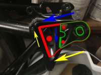
This is the first design, which I think will provide enough support for the current 1000 watt motor, and using regen. The green .
arrows are where the forces will be contained when torque is applied for both rotational directions.

The second option extends the torque arm to the second triangle cutout. I will need to mill/file/grind a channel to clear the first triangle section, but this will provide additional support, further from the axle. Because of how the frame tapers out, there is more support along that furthest contour from the axle. Again, the green arrows are where I think the opposing forces will the contained.

If I decide to go with two arms, this is how I would approach the right side dropout. More straightforward that the left side, but I need to fit the derailleur and make sure everything clears.

Any feedback would be greatly appreciated, since I haven't ordered the stainless flat bar material yet. Thanks ahead of time for your advice and expertise.
As part of the conversion, I need to beef up the dropout(s) for using my rear hub motor. The design of the rear dropouts, while beefy, are contoured in a way that I have to plan carefully on torque arm design. The motor is only 1000 watts @48V, running on a 52V pack, but if I decide to go with rear hub with a little more power, I want the torque arm(s) to be able to handle it.
Here's what I have to work with. As you can see, the dropouts are flat for about an inch, then start tapering out. The left side has two triangle openings, and the right has one. Just under 1/4" thick at axle end. I will be using pins that will fit into the openings of the frame for strength, but using Devcon or other high content steel epoxy to fit within the contours of those openings. I'll be using release agent so that the arms can be popped out after the epoxy cures. The Devcon and pins, which will conform to the openings, will provide a tight fit with no movement.
My current thinking is to design an arm for the left dropout, so I don't need to work around the derailleur. My plan is to leverage the contours of the frame as much as possible to create the anchoring points for the arm. I want the arm(s) removable, since I still may go with a mid-drive at a later time. I will be using, at minimum, 1/4" stainless flat bar.
This is the first design, which I think will provide enough support for the current 1000 watt motor, and using regen. The green .
arrows are where the forces will be contained when torque is applied for both rotational directions.
The second option extends the torque arm to the second triangle cutout. I will need to mill/file/grind a channel to clear the first triangle section, but this will provide additional support, further from the axle. Because of how the frame tapers out, there is more support along that furthest contour from the axle. Again, the green arrows are where I think the opposing forces will the contained.
If I decide to go with two arms, this is how I would approach the right side dropout. More straightforward that the left side, but I need to fit the derailleur and make sure everything clears.
Any feedback would be greatly appreciated, since I haven't ordered the stainless flat bar material yet. Thanks ahead of time for your advice and expertise.