Increasing controller power to my 1000W DD hub motor

Jan-Erik-86

100 W
Joined
Jan 23, 2019
Messages
110
Hi,

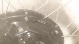
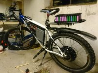
I currently have an unknown 1000W DD hub motor from ebay, and all i know about it is that it's old, and the guy I bought it from say he think it's a 4T motor.
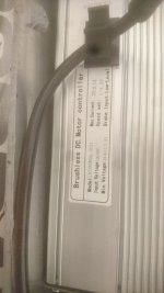
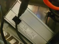
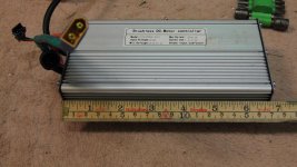
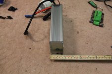
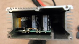
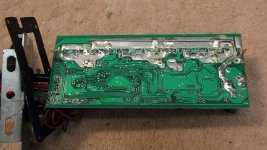
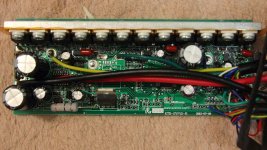
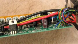
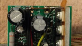
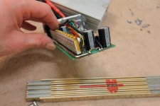
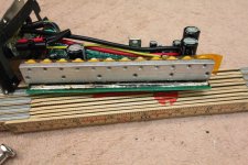
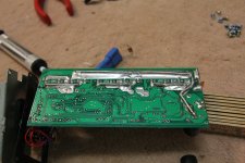
The controller is a 48V 26A max KT controller, and from the model name i assume it's a 21A rated controller? It's a simple square wave, and from the size and current rating I assume it's probably a 12-fet, but i've not been able to verify this yet as it's currently glued stuck.
I use an LCD3 display, and during load i get a reading of around 1100W with a 13s battery fully charged.
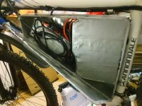
I've attached some pics, so if anyone recognize what motor and controller i have and have more details about them that would be great! :)

In general I'm OK with my current max speed of around 45km/h with a fully charged battery and usually cruise around 25-35km/h anyway, but what i wish for is some more power for short steep hills and acceleration. I'm hoping for something in the 2kw range.

I've been doing some searching, and figured that other then changing my battery from a 13s to a 14s (planned upgrade), the first step for more power would be the controller, and my plan here was mainly one of two:
1: Shunt mod it for more current, and If the stock fets are poor, replace them with IRFB3077 - which I hope 12 of should handle 2+kw?
2: Replace my current controller with a 45A max 18-fet sine controller.

While a controller replacement would be the quickest and easiest, a shunt mod and fet replacement won't be difficult either, and would allow me to still use my physically smaller controller. Being awere the downside would be square wave instead of sine, 12-fet vs 18-fet (but at least the 12 fets would be good quality), and incorrect power reading on the LCD3 display, I would still prefer this option if possible?

But then is the other question - will the motor likely handle it? I know i should probably upgrade the phase wires, but will it be enough to upgrade them until right outside the motor, or will i need to replace them all the way to the inside of the motor?
As for cooling the motor, I will be adding ferrofluid, and maybe cooling fins if needed.
Note that i don't live in a very hilly area, and i won't be needing full power for long periods, usually no more then 30 sec.

Hopefully someone can point me in the right direction here... :)
 

Attachments

  • photo6008166876804394729.jpg
    photo6008166876804394729.jpg
    153.4 KB · Views: 3,345
  • photo6008166876804394728.jpg
    photo6008166876804394728.jpg
    77.1 KB · Views: 3,344
  • photo6008166876804394727.jpg
    photo6008166876804394727.jpg
    115.1 KB · Views: 3,344
  • photo6008166876804394724.jpg
    photo6008166876804394724.jpg
    48.9 KB · Views: 3,345
  • photo6008166876804394726.jpg
    photo6008166876804394726.jpg
    168.2 KB · Views: 3,345
Thank you for the feedback on that.

I know it's not ideal and I've considered to move it out of the box to increase cooling, but on the other side I thought it would be good to have it fully protected from dirt, rain, snow and road salt. The bike have already gone ~5000km without any issues, but I could easily install a sensor on it to monitor the temp if i shunt mod it (or of course move it out of the box if it turns out to be needed). :)
 
To increase power you will likely need a stronger controller. You can do a shunt mod to gain amperage but you can only go so far with what you have(maybe gain 10a), I wouldn't bother wasting time changing all the mosfets unless they fail.

You can check out lyen controllers just google it he sells good stuff thats customizable
also you can check Kelly controllers and get maybe a 50a controller, id get a 72v and program it down for 14s since you may want more later. But after you upgrade the controller you will likely start having battery issues since you will need something capable of producing a lot of amps 45-50a peak under load

Your motor should be able to run about 2000w continuous with 2500-3000w bursts depending on how heavy you are and how steep of terrain you ride. You can also smoke your motor on a large steep climb in 10 minutes if your not careful
 
You say it's recommended with a new controller, but just out of curiosity, is this because even 12 good fets are not going to be enough, or are there other limiting factors in my current controller that would cause issues?
I checked some of lyen's controllers, and it appears they use 4110 fets, which i belive actually run a bit more hot then the 3077 i was considering, but they supports higher voltage though. Kelly's controllers didn't appear to specify what or how many fets are used from a quick look. Though, neither of these controllers are compatible with my LCD3 display, are they?

The alternative controller i was looking at was this: https://www.ebay.com/itm/Electric-controller-Brushless-Sine-wave-ebike-18-Mosfet-45A-48V-1500W-2000W/332849503195
Would this be a bad option?

When you say my motor should handle around 2000W continuous, do you then mean stock, or is this after upgraded phase wires, adding ferrofluid cooling, and maybe cooling fins?
10 minute climbs are not going to happen, my steep hills are short, from 30-200 meters only. :)
 
I have some generic "48v" 15FET controller that was "rated" for around 30A, got peaks of around 33-35A ish. It had two shunts in it. I added a third shunt (from some random dead controller) in parallel with the first two , and that upped it's limit to around 80A. I have no idea what the original shunt or new shunt values are, it was just an experiment to get more oomf from a cheap controller with as close to zero effort and cost as possible. :)

So far, it's still working on SB Cruiser, and it sees that 80A ish peak every day dozens of times during my work commute in traffic, for seconds at a time. I have no idea if it would last if I kept pushing that limit up a hill, at least not any longer than it takes to go up some of the canal-path road-underpasses, which is under 30 seconds.

Some time back, I had an 18FET controller from someone that had been shuntmodded by addng solder to the shunts, and again I don't know the before/after values, but the contorller itself failed when used on CrazyBike2 for acceleration testing...something that works fine with the 15FET modded controller with a more power-hungry motor on the much heaver SB Cruiser trike.

So...a shunt mod may get you quite a bit more power, but it might also destroy the controller, if it heats too much inside. (it's also not just up to the FET specs, but also how the controller drives them; sometimes it's done well, and sometimes nto so much...the latter can result in more heating for the same conditions otherwise, and earlier failure under "overclocking" conditions).


If you're planning on replacing the controller anyway, if it doesn't do the power you want once modded, it won't hurt to try a shunt mod. :)
 
An increase from 30A to 80A sounds almost a bit crazy... :D

I originally didn't intend to replace my controller, but I am prepared to do so if i have to, knowing there probably are limitations on my current one. I was hoping to keep my LCD3 system though.
I must admit that even though I used to work a bit with electronics, I'm not too familiar with FETs yet, and I didn't think about the FET drivers as i thought that FETs only required the correct driving voltage and perhaps a µA of driver current. Is the driver usually an issue when replacing controller FETs?

I've been looking some more at the Lyen controllers, as well as some from em3ev, and i must admit they do look look like a good upgrade. Do i understand it so that i could get a 48-72V controller for example, and then program it to run at say a 13-14s battery pack for now, and easily reprogram it at a later point if i decide to upgrade to a 72V battery? If so, this does sound like a good option to future-proof the system (one will always want more power in the future, eh?). :)

As for the battery, I know I'll probably get issues with high amp draw over time, but I know my current 13s pack will at least handle bursts of ~2kW (i've tested this), so I'm not not worried about the battery as long as i stay in the ~2kW range. :)
 
So I think I've got almost the same controller as you. It's a 12 Fet but it actually looks smaller than yours... Few things I'll note. 12 Fet should be fine. Im routinely pulling 2200w from mine with a shunt mod and that's it...no problems whatsoever. I changed out every cable in the controller. 10awg phase wires and 10awg battery wires. Changed the sensor wires with waterproof connectors and enabled regen via a solder pad. I use 2 u bolts to bolt the motor to the downtube of my seatpost at the bottom of my frame right along the rear tire fender... Ive used a ton of liquid electrical tape to seal up the silicone grommet that the wires go though the controller. I've had it freaking pouring out a dozen+ times and I have no water issues with the controller whatsoever.

I think your biggest hold back will be the battery. What battery do you have? Mine right now will limit me to a second or two burst to 2200w with huge sag. The new battery should easily deliver at least 2000w consistently.

The 12 Fet IMHO is likely the best compromise between power and size. There's some "1500w" eBay controllers out there that are freaking huge so I'm not complaining mine can put it out. I don't know what fets are on my controller but it barely gets warm even in the hot summer which leads me to believe I've got plenty of headroom.
32193997727_16f3b2be46_b.jpg

My only beef is it's not black... I tried quickly painting it black and it's already chipping off without any etching primer..
 
Thank you for the information and picture. I will compare the inside of my controller with your pic and see if it indeed is the same or not. :) If you're able to get ~2kW from it and still keep it cold that sounds perfect, and would be all i'd need.

I'm using two batteries in parallell, one 13s7p and one 13s5p. The 5p is with mixed li-ion laptop cells, and the 7p cells are unknown. Combined they measure ~28Ah at ~0.5c load. I don't remember what the voltage sag was at 2kW load, but i could re-test this.
I only tested it for a few sec at a time, since the UPS i use to load test the battery was reaching overload with a 2200W load.
I will only need full power for a few sec at a time though, as i usually only need 3-500W once i get up to speed.
 
Jan-Erik-86 said:
I was hoping to keep my LCD3 system though.
As long as you get a KT brand controller, it should still work (though you might have to add the wiring to connect it). There's also firmware by Casainho, Stancecoke, and others, in various threads around the forum, that replaces the KT and LCD3 firmware with more programmable stuff.


I must admit that even though I used to work a bit with electronics, I'm not too familiar with FETs yet, and I didn't think about the FET drivers as i thought that FETs only required the correct driving voltage and perhaps a µA of driver current. Is the driver usually an issue when replacing controller FETs?
Not really, but it does make a difference in how well they operate, and a driver stage designed for the FET you use in the way taht you use it will work better than just a generic one.

A FET takes a certain amount of current to charge up the gate to it's trigger voltage range, and the lower current the driver makes the slower that happens, and the more heating that occurs in the FET during the transition from off to fully on and vice-versa. Different FETs take different amounts of charge to switch, so the same driver circuit works differently for different FETs.
 
Philaphlous said:
So I think I've got almost the same controller as you. It's a 12 Fet but it actually looks smaller than yours... Few things I'll note. 12 Fet should be fine. Im routinely pulling 2200w from mine with a shunt mod and that's it...no problems whatsoever. I changed out every cable in the controller. 10awg phase wires and 10awg battery wires. Changed the sensor wires with waterproof connectors and enabled regen via a solder pad. I use 2 u bolts to bolt the motor to the downtube of my seatpost at the bottom of my frame right along the rear tire fender... Ive used a ton of liquid electrical tape to seal up the silicone grommet that the wires go though the controller. I've had it freaking pouring out a dozen+ times and I have no water issues with the controller whatsoever.

I think your biggest hold back will be the battery. What battery do you have? Mine right now will limit me to a second or two burst to 2200w with huge sag. The new battery should easily deliver at least 2000w consistently.

The 12 Fet IMHO is likely the best compromise between power and size. There's some "1500w" eBay controllers out there that are freaking huge so I'm not complaining mine can put it out. I don't know what fets are on my controller but it barely gets warm even in the hot summer which leads me to believe I've got plenty of headroom.
32193997727_16f3b2be46_b.jpg

My only beef is it's not black... I tried quickly painting it black and it's already chipping off without any etching primer..

hi i was just wondering how you could fit 3 lots of 10awg wire through 1kw hub motor. Also ive seen on youtube karma bikes cut the current sense wires going to the main ic solder in a potentiometer where the shunts where to adjust amperage.if anyone tries it be sure to let me know
 
That looks like the same motor and controller I have on my Kona e-bike, right down to the "High Power" sticker on the wheel. I bought the kit back in 2015 from ebay seller, xccessories (spelling?)
 

Attachments

  • IMG_0408.JPG
    IMG_0408.JPG
    239.7 KB · Views: 3,210
Yungyakz said:
Philaphlous said:
So I think I've got almost the same controller as you. It's a 12 Fet but it actually looks smaller than yours... Few things I'll note. 12 Fet should be fine. Im routinely pulling 2200w from mine with a shunt mod and that's it...no problems whatsoever. I changed out every cable in the controller. 10awg phase wires and 10awg battery wires. Changed the sensor wires with waterproof connectors and enabled regen via a solder pad. I use 2 u bolts to bolt the motor to the downtube of my seatpost at the bottom of my frame right along the rear tire fender... Ive used a ton of liquid electrical tape to seal up the silicone grommet that the wires go though the controller. I've had it freaking pouring out a dozen+ times and I have no water issues with the controller whatsoever.

I think your biggest hold back will be the battery. What battery do you have? Mine right now will limit me to a second or two burst to 2200w with huge sag. The new battery should easily deliver at least 2000w consistently.

The 12 Fet IMHO is likely the best compromise between power and size. There's some "1500w" eBay controllers out there that are freaking huge so I'm not complaining mine can put it out. I don't know what fets are on my controller but it barely gets warm even in the hot summer which leads me to believe I've got plenty of headroom.
32193997727_16f3b2be46_b.jpg

My only beef is it's not black... I tried quickly painting it black and it's already chipping off without any etching primer..

hi i was just wondering how you could fit 3 lots of 10awg wire through 1kw hub motor. Also ive seen on youtube karma bikes cut the current sense wires going to the main ic solder in a potentiometer where the shunts where to adjust amperage.if anyone tries it be sure to let me know

Take a look at the ebike review section. Some dude put like 6awg in his... Replaced the fets, added more cooling... I guess he's going for like 6kw through it. Lol its quite easy, 10awg isn't that big..especially for the phase wires. I was originally thinking 6awg for my phase wires but that's total overkill for like 2kw. The weakest link in my electronics now beyond the Chinese cells of my old battery are the phase wires inside the hub motor...they're 16awg. I've seen people slip 10awg through the shaft but that may be for another day...
 
Thank you for all the replies guys! :)

By the way, does anyone know the pinout of this connector? I couldn't find this exact connectors pinout. Phase wires are obvious, but i'd like to know the rest to make things a bit easier.. :)
I guess if i'm aiming at no more then around 2kw peek, there is not much need to replace the wires all the way, as long as i replace them from the controller until right outside the motor, right?
If i do need to replace them all the way i'll order some ferrofluid and install a temp sensor at the same time.
 
I tested the controller now, and it apears to draw around 24-25A peek when LCD3 show ~1050W and battery is down to about 50% SOC.

Eventually got the controller out and apart. It's a 12-FET controller, and It looks like the PCB traces have been slightly enhanced, but there is for sure room for huge improvement as far as that goes. There was almost no thermal connection between the FETs and the controller housing, but I'll do something about when i put it back together. :)
The FETs are 80NF70 by ST, 68 V, < 0.0098 Ω, 98 A. Any ideas how much battery current i could expect to safely draw with these FETs (I will keep an eye on the FET temp)?

Also, any ideas where that one loose white wire should connect to on the board, and what it's for? It goes together with the phase wires, but don't have any solder on it, so it have clearly never been used. Motor temp sensor maybe (it always showed 15c regardless of temp)?
 

Attachments

  • IMG_5047.JPG
    IMG_5047.JPG
    454.9 KB · Views: 3,178
  • IMG_5051.JPG
    IMG_5051.JPG
    357.6 KB · Views: 3,176
  • IMG_5053.JPG
    IMG_5053.JPG
    286.9 KB · Views: 3,176
  • IMG_5065.JPG
    IMG_5065.JPG
    433.8 KB · Views: 3,177
  • IMG_5080.JPG
    IMG_5080.JPG
    441 KB · Views: 3,176
  • IMG_5084.JPG
    IMG_5084.JPG
    357.6 KB · Views: 3,177
  • IMG_5087.JPG
    IMG_5087.JPG
    360 KB · Views: 3,177
I'm not sure exactly how many amps it will handle, but know its ok at 0.5c long term, and i expect it to be ok at bursts of 2c or so. so about ~14a long term and ~50a burst for a few sec.

I removed that small wire that was already there to enhance the PCB traces, and soldered on a thicker copper wire instead. 2,5mm2 underneath and 1,5mm2 at the top (had to reduce it to avoid it from touching the casing and shorting out). Added a proper amount of thermal paste between casing and FETs, and added a temp sensor on the FETs to keep an eye on them.
Board should handle current well now, as well as cool down trough the casing, where it previously would barely transfer any heat.

I then added some mass to the shunt, put it together and did a current measure. First measure using the break to near stall the wheel with full throttle showed 45A, a bit on the high side i guess?
Redid the shunt, but i must have just moved the solder rather then removed it, as my next measure turned out to be 54A.
Redid it once more and ended up with a 36A max current, which I'm OK with for now at least. I'm guessing if i keep the FETs cold enough, this shouldn't cause any issues, right?

I did some outdoor testing for about 5-10 min with multiple start and stop, as well as a few short hill climbs, and there was no issues as far as i could tell, other then the phase wire connector (not the wire itself) getting rather warm. I had already made sure to spray the connectors with contact cleaner followed by electronics cleaner, so i know it's not a poor connection, just a connector not able to handle the load. Will look into how to solve that, but for now it should work fine
After this "harassment" for 5-10 min, the FET temp had increased with around 10-11c, but this was after bringing it from 17c indoor to 2c outdoor temp though.. What would be a safe max temp to let the FETs reach?
 
Be careful of testing up long steep hills once then twice or wet sand ect. If it isn't flying ez be careful . Do the Johncr hand temp test. If you're lugging it it's making Heat.
 
Thank you for the advice, I am trying to be careful. :)

Outdoors I tested with using PAS first, gradually increasing it from level 1/5. Seeing that PAS 4/5 now give around same power as 5/5 would before mod, i gave 5/5 a go and it read around 36A/1600W. No parts got hot to the touch after 5-10 minutes, but the phase wire connectors did heat up, and i don't like that. Any heat is power lost and potential damage in connectors, so I will find a better connector as my next step on the way, together with replacing the super thin phase wires.

Adding some pics of how it turned out.
 

Attachments

  • IMG_5103.JPG
    IMG_5103.JPG
    398.9 KB · Views: 3,150
  • IMG_5098.JPG
    IMG_5098.JPG
    337.7 KB · Views: 3,150
  • IMG_5096.JPG
    IMG_5096.JPG
    364.8 KB · Views: 3,150
  • IMG_5090.JPG
    IMG_5090.JPG
    417.2 KB · Views: 3,151
I've now added some phase wires and done another quick test.

I still left the stock (0.75mm2?) phase wires in place, but i also added new 1.5mm2 wires all the way from controller PCB to right before the hub. Nothing blew up, and nothing got warm, but I'm not sure how to read my "new" power usage data...
I suspected my cheap watt meter to have limits, and comparing the LCD3 to the watt meter it's clear that higher loads affect it.
These are my new readings, compared to what peeks the LCD3 shows at different PAS settings:
1/5: 140W = 326W +133%
2/5: 240W = 495W +106%
3/5: 400W = 764W +91%
4/5: 550W = 1035W +88%
5/5: 1000W = 1702W +70% (37A according to cheap watt meter)

So, as i don't have a DC clamp meter, i can't confirm actual current draw. All i know is that both LCD3 and cheap watt meter agreed on around 1100W before the mod (24A according to cheap watt meter). So, i guess until i get a more accurate meter i should assume around +88% power? Would this likely be a safe increase on my FETs as long as they are kept cold enough?
 
Did some more testing today, and went for a ride around 12km with medium/high power usage, significantly more then I'd ever normally need.

Start temp was around 12c before i went outside. Outside temp was around 4c. After the ride, the max temp the FETs reached was around 18c, so cold in fact i had to put my hands on the controller to confirm it was really that cold and not a faulty temperature probe. All other components stayed cold as well.

I guess it's mostly mission complete for now then, and time to put all the covers back on and seal it off to make it waterproof again. :)
 
Looks good man! holy crap that's a ton of thermal paste! Looks like the holes and solder points for the phase wires are freaking huge compared to the actual wires...whereas my controller is the opposite..

I found after taking my battery apart to replace it with a genuine panasonic cells one that my limiting factor was the battery. I can't wait to complete my new battery and check out the power. I'm going to be pulling some serious power!
 
Thanks! Yeah there was a bit much thermal paste, but i reapplied it after replacing the phase wires, so now it looks much more clean. It's none-conductive though, so no risk of shorting anything. :)

And yeah, the phase wire holes on the PCB would take at least 2.5mm2 wires, maybe even 4mm2.

You say your battery was the limit, but in what way? Too much voltage sag to get the power when needed? My battery is near fully charged now, so I'll soon give it another go to see what voltage sag i have on a full battery.
 
Jan-Erik-86 said:
Yeah there was a bit much thermal paste, but i reapplied it after replacing the phase wires, so now it looks much more clean. It's none-conductive though, so no risk of shorting anything. :)

It's probably not the issue being described, but keep in mind that too much paste between a heatsink and the object it's cooling can actually cause a problem later on, as the paste dries out and leaves an airgap, which is worse than having no paste at all to start with.

What you really want with any paste is to *only* fill the scratches and other airgaps between the two metal surfaces, so that all possible surface area directly contacts each other, and the paste just eliminates any airgaps and makes for more full-contact surface area for better cooling.
 
if you do a shunt mod and chnage fets make sure you upgrade the traces on the board and install thicker wire everywhere maybe 10 awg on everything
 
Back
Top