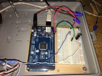
I have a 500w non-hub motor that I want to completely control with an Arduino. I don't want to use the hand throttle. I'm going to have a program where I tell it different commands, like "go forward at x speed for 10 seconds" etc.
I have Sunfounder Mega 2560. I spent a lot of time trying to get it to control the throttle but it's not working. The best I could do was make the motor make clicking sounds. I tried to create a low pass filter with a resistor and capacitor but it didn't work. I also played around with a opticoupler.
One thing I don't understand is.. the motor controller has a positive, negative, and sensor(?) wire. If I was setting the throttle speed with the Arduino, what would I do with the positive wire on the motor controller? I'm not sure if I need to hook all the wires up to the Arduino or just the sensor and the ground wires.
If anybody could help that would be great. I spent a day working on this and it's still not working. BTW this is for a cable-car robot, not a bicycle. I hope it's ok I'm asking here. This seems to be the most knowledgeable forum.
This is a video
https://www.youtube.com/watch?v=EBIFFykNipA
Thanks


