Ideal form of speed reduction for powered bicycles?

svejkovat

10 mW
Joined
May 16, 2009
Messages
29
This is a generalization I've been trying to flesh out by reading the post archives here and posing questions in a few other threads. It's difficult to settle out the pros and cons of various means of speed reduction since most information online pertains to industrial and automotive applications. For an ultra lightweight bicycle, what is considered the ideal? The timing belt to one or two jackshafts with final chain or timing belt would seem to be best for noise. A gearbox is a bit louder but slightly more efficient? Helical gearboxes are superior to spur gear boxes, because increased mesh area delivers more torque per weight/size and lessens noise. But most of the gearboxes that are affordable seem to be simply spur geared.

If low noise and vibration is a premium, and I'm guessing it is for most of you, just how objectionable are some of these approaches?

I realize that it's hard to generalize even within the scope of E-bikes. Exactly where the speed reduction is applied is going to make a difference. To the rear wheel; to the pedal cranks; friction driving the rear tire; etc. But where it can be made to fit the design, are timing belts and jackshafts pretty much the ideal for the efficiency, weight, bulk, performance, and noise goals of a motorized bike?
 
There's a lot of innovation going on right now, and soon there will be a lot of performance data posted, but IMHO, the old phrase "what do you want to do"? is still appropriate.

I believe as more people copy Grinhills RC one-stage belt-drive, it will prove to be very popular. However it must be kept in mind, his goal was a top speed of 27 MPH, and there is only one size of large end-gear available.

When a "high end" enthusiast wants the capability to achieve 40-MPH, you have to consider what is possible with existing parts. You can only go so small on the tiny drive gear, and in truth using the absolute smallest gears available are probably not a good idea. Adding several teeth (and by consequence, some diameter) to the small gear, it quiets the operation and softens wear on the chain/belt. Enlarging the small drive gear should raise top speed, but it also lowers torque and raises motor heat.

Electric motors (per wattage design goal) seem to be more efficient at higher RPMs, and even a non-engineer can appreciate how a fast-spinning motor can dissipate heat better than a slow-spinning motor (Hubmotors come to mind...) The Recumpence single-stage drive might be the most compact, affordable, and appropriate if your speed goal was (I'm guessing) 27 MPH and you are using a 20" wheel. If you wanted 32 MPH, you could perhaps spec a higher kv motor and then up the voltage of the system from 24V to 36V, or even 48V (60V? 72V?...) many options.

If you wanted a higher-power drivetrain, you should immediately consider higher voltages to reduce the amps (heat). Which leads you to higher motor RPM's, and a single-stage might require a very large bull gear. This leads to packaging problems (if the larger gear size you want is even available). One of the clever things about the Recumpence 2-stage drive, is that it can be rotated into several shapes. There are a variety of frames it might be attached to, and a fixed shape (like his "boxed-drive") is much less flexible in getting it to fit a customers project.

Thats why posting real-world performance data in places like E-S is so important. A properly sized motor might get warm on accelleration and hill climbing, but cool off during the 80%+ of a ride when you're just cruising. But, a "too small" motor & controller getting fried from too much heat... that would be a waste of money when you thought you had saved a few dollars on the design you chose.

Every added stage adds capabilities, but it also adds complexity, cost, and friction. I think I sense a frustration in your post as to "if the best minds here havent determined whats the 'best' configuration, what chance do I have of getting it right the first time on this $1,000 project I'm contemplating"?

Select a frame and wheel diameter, then choose top-speed desired, then measure range desired (to work and back?) and post if you have lots of hills or flat land. At that point you can then spec out several drive configurations with exact components, and ask for a review evaluation for possible strengths and weaknesses in the various choices.

I'm going to go out on a limb and say that a hub system like ampedbikes.com will probably remain the simplest and most cost-effective entry-level choice. However, for a variety of engineering reasons, I believe the recent RC experiments will establish that they are the highest performance, smallest, lightest systems available. Also efficiency (heat rejecting ability, greater range for the same amp/hour of battery) will measurably be significantly better.

Just a few thoughts, I hope they helped...
 
spinningmagnets said:
There's a lot of innovation going on right now, and soon there will be a lot of performance data posted, but IMHO, the old phrase "what do you want to do"? is still appropriate.

I believe as more people copy Grinhills RC one-stage belt-drive, it will prove to be very popular. However it must be kept in mind, his goal was a top speed of 27 MPH, and there is only one size of large end-gear available.

When a "high end" enthusiast wants the capability to achieve 40-MPH, you have to consider what is possible with existing parts. You can only go so small on the tiny drive gear, and in truth using the absolute smallest gears available are probably not a good idea. Adding several teeth (and by consequence, some diameter) to the small gear, it quiets the operation and softens wear on the chain/belt. Enlarging the small drive gear should raise top speed, but it also lowers torque and raises motor heat.

Electric motors (per wattage design goal) seem to be more efficient at higher RPMs, and even a non-engineer can appreciate how a fast-spinning motor can dissipate heat better than a slow-spinning motor (Hubmotors come to mind...) The Recumpence single-stage drive might be the most compact, affordable, and appropriate if your speed goal was (I'm guessing) 27 MPH and you are using a 20" wheel. If you wanted 32 MPH, you could perhaps spec a higher kv motor and then up the voltage of the system from 24V to 36V, or even 48V (60V? 72V?...) many options.

If you wanted a higher-power drivetrain, you should immediately consider higher voltages to reduce the amps (heat). Which leads you to higher motor RPM's, and a single-stage might require a very large bull gear. This leads to packaging problems (if the larger gear size you want is even available). One of the clever things about the Recumpence 2-stage drive, is that it can be rotated into several shapes. There are a variety of frames it might be attached to, and a fixed shape (like his "boxed-drive") is much less flexible in getting it to fit a customers project.

Thats why posting real-world performance data in places like E-S is so important. A properly sized motor might get warm on accelleration and hill climbing, but cool off during the 80%+ of a ride when you're just cruising. But, a "too small" motor & controller getting fried from too much heat... that would be a waste of money when you thought you had saved a few dollars on the design you chose.

Every added stage adds capabilities, but it also adds complexity, cost, and friction. I think I sense a frustration in your post as to "if the best minds here havent determined whats the 'best' configuration, what chance do I have of getting it right the first time on this $1,000 project I'm contemplating"?

Select a frame and wheel diameter, then choose top-speed desired, then measure range desired (to work and back?) and post if you have lots of hills or flat land. At that point you can then spec out several drive configurations with exact components, and ask for a review evaluation for possible strengths and weaknesses in the various choices.

I'm going to go out on a limb and say that a hub system like ampedbikes.com will probably remain the simplest and most cost-effective entry-level choice. However, for a variety of engineering reasons, I believe the recent RC experiments will establish that they are the highest performance, smallest, lightest systems available. Also efficiency (heat rejecting ability, greater range for the same amp/hour of battery) will measurably be significantly better.

Just a few thoughts, I hope they helped...

This is one of the most beautiful posts I've seen on Endless sphere. I think a tear of happiness wants to streak.
 
I doubt a firm answer will come out of this thread, but it might be helpful to many of us if someone can post info about some of the specifics that could help guide these decisions. Expected efficiency losses per stage by type would be especially helpful (at least to me). eg I understand that a well maintained derailleur chain drive can be 97% efficient, so I'd expect a single reduction chain stage can be even better as long as the reduction ratio isn't too large. What efficiency is possible with belts?...spur gears?...helical gears?...How much does efficiency suffer if you add a lightweight oil to help silence and reduce gearwear for an otherwise noisy gearbox?...What are the smallest recommended gear and pulley sizes for the drive side for different sizes of chain and types of belts?...Up to what torque and rpm are freewheels durable? How much torque and rpms are different chains and belts viable.

The answers to these along with other useful rules of thumb would be quite helpful as a sticky. As my small contribution, I have sound measurement tools, and I already planned to test (both dry and in a light oil) my angle grinder reduction gearboxes that contain durable heavy duty helical beveled gears. I also have a variety of chain sizes and sprockets, so I do sound measurements on those too?

Is this a waste of time though? I have to believe that there are already 2 or 3 speed transmissions in the works that are sufficiently compact and lightweight to meet our needs. If not, then we need to get together and come up with one, unless gears are that much less efficient than belts or chains.

John
 
This is one of the most beautiful posts I've seen on Endless sphere. I think a tear of happiness wants to streak.

Hear, Hear!

Well summarised, spinningmagnets :D
 
This exact thing is making my mind melt
I have a powerpack brushless motor I want to use a 36V 30Ah LiFePO4 pack to run it. It spins at 3,116 RPM under load and never gave me any problems when I used it on a scooter so it is proven. The question is how to gear it down? A 15mm wide belt with a 14T motor and 72T on a crank axle? That drops the RPMs down to 605 but I want it to run to a 13-34T rear cassette. I can throw a 22T on the crank to drop the gearing again but I won't be able to pedal.
Right now I'm looking for a 4 or 8 to 1 reduction box to make this thing work. Heck, I'll take a regular bike chain reduction box that spins an 11 tooth motor sprocket to a 52 tooth crank sprocket for a nice 4.727 speed reduction. That would drop the RPMs down to 660 and use a belt drive 14/72 on the left hand side to the crank axle for a max speed of 128 RPM. Now it becomes "doable" so my rear wheel can be a 13-34T cassette, Nexus 7 speed hub or Fallbrook CVT-P.
I am happy I'm not trying to use 7,500 RPM RC motors! 3,100 RPM is enough to think about. A belt drive in the reduction system would work well, it will quiet the thing down and prevent shock and driveline snap to rear hub gears. A dual-stage belt drive system to tune a 10 to 40 to 1 speed reduction would work well with most motor drives. Since I'm dreaming, make it able to handle up to 5KW of power.
 
I'm not qualified to state that one type of drive is "better" than another configuration, I can only gently suggest that each layout may have its own strengths and weaknesses.

Another big problem with contemplating different gear-downs is where to put a freewheel. If everything in the driveline has a solid connection then when you are pedaling, your feet will be driving the motor as a generator, which is a serious physical drag. Several have found a way to use the cheap TNC freewheel (10?) which is easily available, but it wears out quickly. Others have upgraded to the more expensive White Industries ENO and nobody has worn one out yet (as far as I know).

However owners of both say when just pedalling, the pawls of the freewheel make a lot of noise. I have seen a large one-way bearing from CSK that may work well silently, but there's no obvious way to "slap one on" yet. Grinhill is using a tiny one-way roller bearing, but he was looking for ways to adapt a larger one that would be stronger and longer lasting.

I have read some discussion about using a small 3-speed transmission from a drill (suggested by a home-built robot site) but there haven't been any projects with it yet to evaluate them.

I have seen several builds using a compact planetary gear-down on the motor shaft, and the builder sounded satisfied with it. I've seen a couple 90-degree angle-grinder-head drives, but nobody sounded happy with them.

For simplicity and cost-savings, many young builders try very hard to make a single-driveline from motor to wheel, with a giant gear on the wheel, and the tiniest motor gear. Those who have tried this have found a chain on a tiny high-RPM gear makes a LOT of noise and will wear out quickly. Using a larger motor gear quiets the chain, softens wear, and raises top speed, but loses torque and makes motor heat worse. So then you realize you're forced to add a stage.

For high-RPMs, belts are much quieter than chains. I believe Recumpenses belted single-stage is a 5:1 If that isn't enough reduction, you would have to use a much larger bull-gear (if a bigger one is even available) and a bigger gear would also make it harder to package and mount. Speaking of mounting, one of the clever things about Recumpences 2-stage drive is the parts can rotate into different shapes, making it easier to mount to the different shapes of bike-frames.

The reason many builders prefer to use a chain for the 2nd stage (when a 2nd stage is needed) is that chains are stronger (the 2nd stage is under much more load than the first). They are also thinner, and there is a wide choice of off-the-shelf (OTS) sprocket ratios available.

The small gear of a chain stage should always be steel, but the large gear has sometimes been made of aluminum or plastic with good results because the load is spread over many teeth.

Motor reduction drives are still a complex subject without a single "master calculator". Your initial project math may call for a 5-1/2T motor sprocket, when the smallest available is 11T Then you realize the smallest freewheel you can find requires at least a 24T gear, throwing all your math off. Several builders have had to drill out the shaft mounting hole of a pulley (risky), because the hole diameter they needed wasn't available...If you post your wheel diameter, top speed desired, and motor you have/want...the closest pulleys/gears available should be fairly easy to spec.
 
spinningmagnets said:
owners of both say when just pedalling, the pawls of the freewheel make a lot of noise

Has anyone tried spraying light oil, for instance triflow, onto the area where the pawls strike? I don't have a noisy freewheel to try it on, but that's what I used to use 30 years ago and it quieted the freewheel with out introducing noticeable drag.
 
I have finally figured out the drive!
My Powerpack brushless motor runs at 3,116 RPM at 20 amps and 2825 RPM at 35 amps under load. I'll get one of those frame extensions that extend the bike back another two feet. That will leave the stock axle location unpopulated. I'll take a rear hub with disk mount in the 130mm roadie size and use it as a jackshaft. Instead of a disc, I'll put a 60 tooth gear that mounts to the disc mount and it it offset for extra frame clearance. To add more clearance, I'll get a longer solid axle and stack more nuts on the left side to shift it farther right to clear that large gear. Throw an 11 tooth sprocket on the motor and have a 5.456 gear reduction. That will spin the "jackshaft" hub at 571 RPM at 20 amps and 518 RPM under load at 35 amps.
On the other side of the hub, I'll run a few gears off a cassette with an 11t on the end that drives the rear wheel. I'll throw two 12t gears next to the 11T so the chain from the pedal crank will engage that gear. The crank gear will be a 60 tooth steel monster from a recumbent. This will spin the cranks at a max speed of 114 RPM through it's 5 to 1 reduction to the crank. It will be a freewheel crank with the ENO freewheel so I'm good there.
The back wheel will run an 11-34t eight speed so I can go at 9.6 MPH in first at max load and 35 amps and 30 MPH in 8th gear at 35 amps. At less than max load, it will push me along at almost 33 MPH. The rear wheel will be a 20" BMX 48 spoke beast so I can get that really low gearing. Front wheel will be a 24x3.0 for great traction and a stiffer front wheel. Luckily, I will use a Norco One25 frame which has a very high crank so the back wheel won't kill it too much. That frame extension helps matters with the crank also.
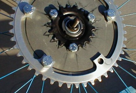
To get a monster 60 tooth crank gear on a freewheel crank is not too hard. Take the stock solid 48t and drill 5 holes in it to mount the regular chain ring on it in a 130mm bolt pattern. I have burned rubber on my scooter running the 36V 35 amp power pack motor when it was geared for 23 MPH max speed (11/90 on a 12.5 inch wheel) I can imagine what kind of acceleration and torque it will give me when geared down to around 10 MPH! :twisted: Since I'll use that frame extension piece with the rear rack, it solves were the battery goes and will give a much more stable ride and must stronger braking due to it's length. I can even hide the "weird" back 20" wheel with the bags that sit on the rack. I'll pay extra for the guys to use the reverse fork (motorcycle style) ears so I can use a conventional motorcycle type device to lock the back wheel in position.
Problem solved except for one thing... my spouse! The battery pack, 20 inch rear wheel and frame extension are the parts I don't have...everything else is sitting on my shelf.
Has anyone used a rear wheel hub for a jackshaft? Those disc brake mount gears can be had up to 80 teeth and the scooter type motors can run bike chain gears down to 9 teeth for some serious reduction if need be. Mount two wheel hubs in an aluminum box and connect two 11-60t gear sets together for a 29.75 to one gear reduction. Would that be enough for RC motors?
 
Sounds like a great idea! As far as anyone else using a hub for a jackshaft, check out this link to Matt's recumbent build...he used one.
http://www.wisil.recumbents.com/wisil/shumaker/default.htm

Good luck with the build...looking forward to some sweet pics.

--Ryan
 
Good find Rizzlo, I'm also looking forward to pics, EVnewbie...

unit7_sm.jpg


framecradle_sm.jpg
 
Thanks for the link, Rizzlo
The Xtracycle frame extension with existing rear dropout for a jackshaft is the solution. Then to figure out the details, that is were the devil resides. :twisted: I learned a lot about belt drives so I want one for the primary bike hub reduction unit. I can get a 15 tooth pulley for the motor and a 72 tooth pulley for the rear wheel axle. Since the 72t is so large, I can drill holes through the disc rotor (even has existing holes!) to hold the pulley inboard of the disc. The stainless steel disc brake rotors will handle the torque easily. Run the GT2 15mm wide belts so there is no chance of shredding the belt since I will be running 36V 35 amps (I can upgrade to 48V if I want) This puts the primary reduction at 4.8:1 or drops the RPMs down to 650 RPM. I really like the idea of using a rear wheel hub for a jackshaft since it is designed for those rotational speeds and I can mount various gear ratios on the thing.
With a 11-34t rear cassette, that puts the MPH range from 11.6 MPH in 1st and 36 MPH in 8th gear which is still the range I want. Under a 35 amp load at full pull the max speed in first drops to 10.6 MPH which would give me the pulling power I need. After reading the fun with recumbents drive problems, I think a 15mm wide belt would be critical to keep the noise down and to cushion the driveline shock when cranking the throttle. Having all that extra space in the Norco rear triangle gives me the room for the rear hub jackshaft. Since the frame extension is made for a 26" wheel, dropping it to a 20" should allow the space for that 72t pulley.
My wife is very nervous about the drawings I have laying around but no worries, it is a winter project for the drive line. We are about to move 1,500 miles so no screwing around with the system at this point. Just drawings and solutions and so far things look good. I had to recalculate gear ratios again because of increase of tire diameter from 1.75" to 3.00 inch that I'll be using. Even with the belt drive mod and taller rear tire, I am still sitting at 11.3 MPH in first gear. Top speed is now 40 MPH in 8th gear so I'll just lock out the derailluer to limit the 8 speed to a 6 speed to keep it down to around 32MPH. My son will ride the thing so it will have to be done.
The only non-off the shelf part would be the belt pulley holes to bolt it to the disc rotor. Not hard to do though, drill holes into the pulley to bolt it to the disc. All is good! I'll even spring for a downhill specific rear hub to make the jackshaft. If I ever nuke the Powerpack motor (doubtful at 36V) I can squeeze in a Mars :twisted: Change the gearing on the cassette from 11t to 16t to drive the rear wheel. At least I won't have to machine a bunch of sprockets. So far, so good!
 
Any idea on the price of one of those harmonic drives (suitable for e-bike needs)? I couldn't find any price info on the Harmonic Drives web site.
 
Excellent topic. I have parts coming for my offroad mountain bike project. The Cyclone 1200 kit
is equipped with a planetary reduction, which I understand sounds like a cat getting strangled. Not
exactly stealth. Seems that a toothed belt would be ideal for the 1st stage of reduction, but I'm not
finding suppliers of large ( 6 " to 8" ) diameter timing pulleys to be able to use. Have any of you found a good source
for big pulleys like that ?
Has anyone tried flooding the gear case of a cyclone geared motor with thick oil to see if it helps dampen the
'cordless drill on steroids' sounds ? Perhaps sealing the case with some O rings and sealer, so it does not leak out...
 
lesdit said:
Seems that a toothed belt would be ideal for the 1st stage of reduction, but I'm not
finding suppliers of large ( 6 " to 8" ) diameter timing pulleys to be able to use. Have any of you found a good source
for big pulleys like that ?

http://www.endless-sphere.com/forums/viewtopic.php?f=28&t=8491
 
Ya, I browsed those links. Nothing chain ring sized, except for the link for the bike that used one.
Looks like I'd have to get one from an existing bike, or machine a custom pulley with the right tooth profile.
There were a couple of 8" ones, but they were cast iron and weighed 7 lbs or so. More suitable for industrial
equipment.

If anyone happens along a nice big timing pulley that might work for a bike, chime in.
 
File under possible hacks...

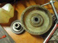
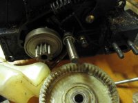
I tore down my electric chainsaw today for cleaning and got a look at the reduction gearing inside:

The motor shaft is ~7mm DD, the small steel cog is 11T. The large nylon gear is 56T, with needle bearings on a ~10mm shaft. The nylon gear seems fairly strong.
IMG_3748_sm.jpg
IMG_3750_sm.jpg
View attachment 2
I rekon a sprocket could be bolted to the face of the large nylon gear with standoffs for chain clearance.
(The steel driver for the saw-chain is bonded to the gear, but also contains bearings.)
 
A friend at work was telling a story about an 84 ford that he had...
He said that the used a nylon sprocket on the cam drive and that it failed on him
in rush hour traffic.

So, I immediately thought, why in the hell would they use plastic in
such a critical application.

But then he told me it had 180,000 miles on it....
and well, that was impressive for plastic.
 
boostjuice said:
HARMONIC DRIVES. If only the efficiency was greater and they were rated to higher input speeds for the higher torque models....

http://www.assag.ch/en/index.cfm/treeID/128

http://www.roymech.co.uk/Useful_Tables/Drive/Harmonic_Gears.html

http://www.harmonicdrive.net/

Yea, those are cool. I have a hunch the efficiency could be improved a bit if the drives were designed with a bit of output backlash.

Sumitomo also makes some interesting gear boxes. These use a similar gearing system with only rigid components.

Lawson
 
Back
Top