2 Speed Planetary Shifter Idea

mclovin

100 W
Joined
Apr 4, 2009
Messages
184
Location
Seattle
2009-06-07_2050.png


2009-06-07_2054.png
2009-06-07_2056.png


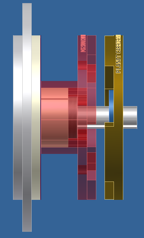
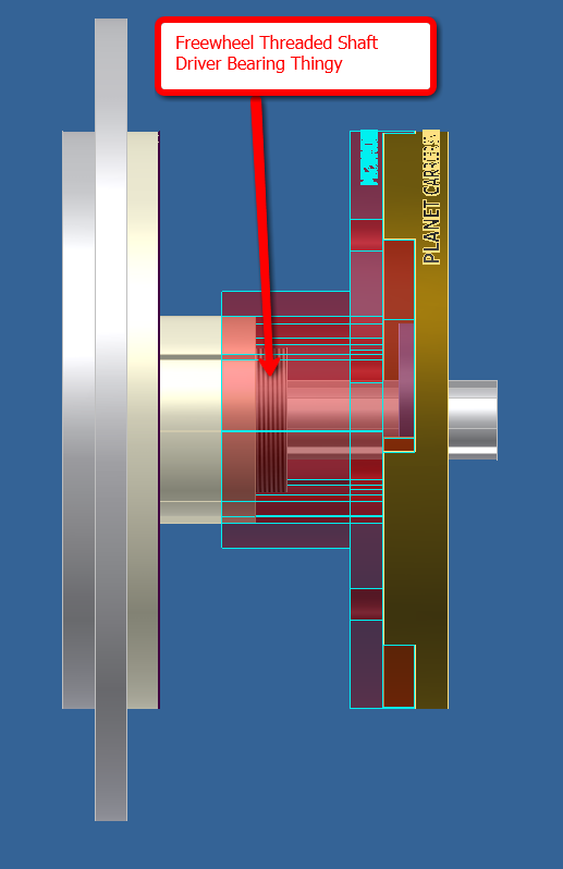
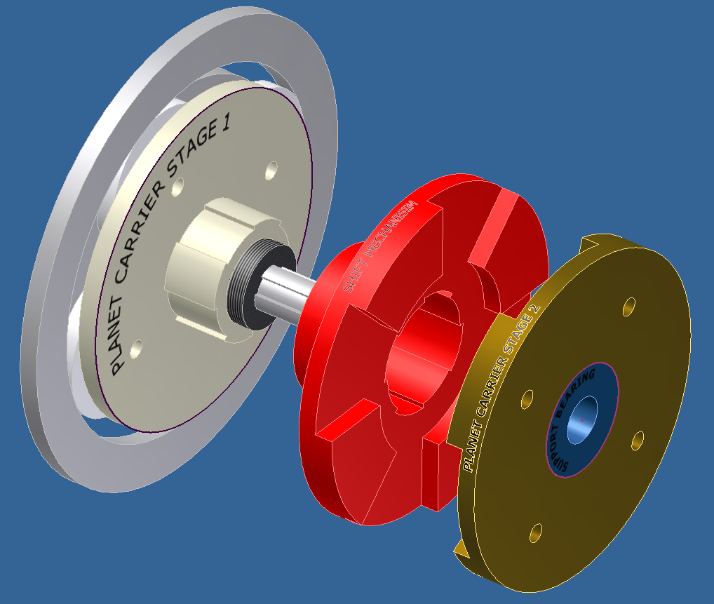
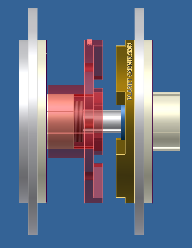
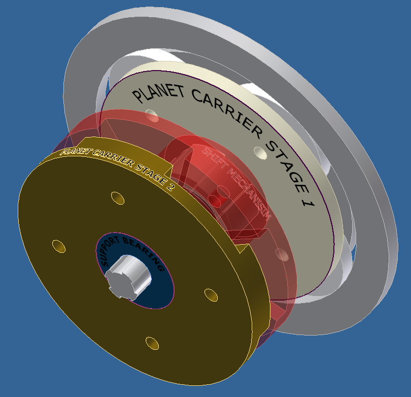
So the idea is that the shift clutch (see thru red part) is coupled with the first stage planet carrier. In low gear the shift clutch is disengaged (to the left in these pics), output from stage 1 drive a shaft via a freewheel mechanism that will be in the "locked" state. During shifting he clutch will slide to the right along a spined support hub and carrier stage 1 will directly drive carrier stage 2. Then the sun gear of stage 2 will drive its input shaft faster than carrier stage 1 is spinning and freewheel.

There would still be a fair amount of engineering to do but I think this (or some variation of it) could work.... :roll:
 
Is the output integrated somehow?
 
gogo said:
Is the output integrated somehow?

I removed all the gears from the output in the images for the sake of clarity. I'll post an image of the complete gear train tomorrow. I hope that asnwers your question.

Cheers.
 
I'm McLovin it!! (couldn't help myself :mrgreen: )

How are you planning on feeding the input, i.e. ring gear?

I was looking at my 62 tooth GT pulley and considered boring out
the center and pressing the resulting ring over the perimeter of the
ring gear. That would allow a belt drive reduction which
is the input to the ring gear. 62:20 would result ~3:1 reduction
before the ring gear. Reducing the speed would also help with noise/gear whine

Since you have two reductions planned. Were you planning
on driving the ring gear with any reduction or direct?
 
I think the input will be via the sun gear with a primary reduction belt drive. But I'm not sure yet. Going through the ring gear looks interesting but I have to think about the packaging arrangemnts and cost implications.

I my try to apply this shifting mechanism concept to the other two speed idea I have as well.

In either case there is still a fair amount of engineering I need to do before I commit to cuttin' metal.
 
Oh, you are planning on producing these? What do you think of making the transition from 1st to 2nd automatic, and maybe making 2nd 1:1 without planetary gears?
 
Yea, packaging a belt drive input off the ring gear like I described would be tricky to seal.
You'd probably want to do a counterbored hub that attaches to the ring.
The hub would need bearings on the id to support the sun gear shaft and
bearings on the OD to the support the ring gear hub. Then you could mount parallel pulleys
or just leave the sun gear short and not drive it.

Then I guess you just pick your poison on the second stage...
i.e. fix the ring and pull the output on the sun,
or fix the sun and pull the output off the ring?
 
The Ford model T had a planetary transmission with two forward speeds and one reverse. All I know so far is that the flywheel had a lip with ID gears so the engine drives the outer ring gear. The shaft (sun gear) is the output. Each planet set carrier plate has a short tube extension that connects the planet carrier plate to a drum.

Each drum has its own pedal that actuates a choke-band (1, 2, R). Choke the slow planets and the car starts moving, choke the fast planets and the output shaft spins faster. It used a wet-clutch and the whole thing was housed in an oil-bath. Reid?....REID?....help a brotha out....

I doubt this has any application in the new RC builds, but I believe this certainly has promise of being a big help for an E-Motorcycle.

trans.jpg
 
mclovin (again, great graphics!) I notice the red and gold elements operate (as one of their functions) as a dog clutch. I had an idea recently, and I've always thought of dog-clutches as very hard engaging, but having a solid connection. The centrifugal Kart clutches aren't very big, but they could act as a synchro.

An electric motor doesnt need a reverse or a neutral. The planetary trans could always start in low, and at X-RPM, the centrifugal actuates and begins engaging in a way that shifts the trans into high. Of course centrifugal clutches constantly slip a little so, normally they wear out quickly.

My idea is that once the centrifugal bell starts spinning, it causes an integrated dog clutch to be pressed together (held apart by a simple coil spring). As the centrifugal continues to slip a little, a few degrees of rotation let the dogs gently drop into their slots.

This way the centrifugal lasts a long time, and the dogs get a solid but gentle engagement. If you slow down and take pressure off them, they disengage under X-RPM's. Many ways to skin a cat (no actual cats were harmed in the writing of this post)...

Her's a pic of a sliding 3-dog clutch:
images


clutch.JPG
 
spinningmagnets said:
Of course centrifugal clutches constantly slip a little so, normally they wear out quickly.

That depends on how they are designed. Its possible to design the clutch arms to increase their locking force by lever action according to power input (after engagement RPM). Then the the clutch would only wear out quickly if you stayed at the engagement RPM too much.
 
Having some type of "active" engagement - I'm begining to think - is essential. Dog clutches are fine within the limitations of what they offer: simple and effective execution of shifting. I have a dog clutch in my 35 year old Moto Guzzi tranny and it has been working just fine all that time - I assume. BUT, when I shift there is a big CLUNK sound. I dig it myself but I could see how someone else might be put off.

Combining a dog and centrifagul clutch sounds like an interesting idea.

The design concern that has been niggling my noodle is what happens to the motor when a simple centrifagul clutch engages? After shifting into high the load on the motor will increase and, ostensibly, the motor will slow down and possibly cause the centrifagul clutch to release. A dog clutch could possibly stop that from happening....or maybe a flywheel........OR I could be totally wrong and it shifts just fine. :lol:

My other concern for a simple centrifagul clutch is its sensitivity to the engement speed. A very refined centrifagul design can be really fine tuned but a simple (i.e. cheap go-cart clutch) may float around the engagment speed. Personally, I just don't know enough yet.

I just ordered a chep go-cart clutch and will model it in a 3D CAD system and test the design dynamics digitally. That may shed some insight. OR if somebody out there already knows a lot about clutches please spill the beans. :)
 
What if the centrifugal clutch engaged not according to input speed, but instead to output speed? That way as long as the motor power was enough to meet the load, acceleration would be slowed after the shift, but output speed and clutch force would continue to increase.

Ya, I have a 1973 BMW 750, and if I back off the throttle while putting pressure on the shifter, it will shift into the next gear without using the clutch. Once I got the hang of it, a "snick" will result instead of the clunk that happens when using the clutch.
 
I believe cargo trikes and E-motorcycles can really benefit from a simple strong reliable 2-speed tranny. For most e-bikes, I doubt it will be worth it with the way the RC drives are quickly developing.

That being said, I think the centrifugal aspect of this is better operated from the output shaft, so gear is dependent on wheel speed. Not quite sure yet of a good way to do that, probably several do-able ways.

There's a 2-speed E-moto thread, and I just posted over there about an "F&P" German bicycle 2-speed automatic. Two centrifugal weights spin out against springs, and at a certain output RPM, they engage a part with a spiral element. When the spiral part moves, it slides over a dog-clutch to lock the input to the output so the second gear is a 1:1. The low RPM gear is 1.36:1 (but if we cobbled one together, it could be a wider ratio).

They advertise its for a tandem bike (power of two pedalers pushing a heavy steel two-seater), and the guts look very rugged. They advertise its cost is 100 Euro's.

I have read of builders putting pretty high power levels (5,000W/7-HP?) through a Nexus 3-speed hub with no problems. I believe they used a trike hub which was advertised as being very stout. The F&P gears look much longer (only one speed + a dog clutch) and very stout.
 
Anybody have a power output curve for a typical RC motor ? Are they really that different of a shape than a 'regular'
motor ?
For an off road bike, I believe that using a transmission is of great benefit. For pavement you don't mind if your motor is bogging a bit
from a stop, because you will quickly get out of the 'bogged down' speed, and commence cruising speed. On an off road bike, there is no cruising speed because the terrain is highly variable. So the motor without a transmission may be forever trapped in a bogged down speed that
optimizes it's function as a heater ;)


spinningmagnets said:
I believe cargo trikes and E-motorcycles can really benefit from a simple strong reliable 2-speed tranny. For most e-bikes, I doubt it will be worth it with the way the RC drives are quickly developing.
 
I think this is what you are looking for...
http://endless-sphere.com/forums/viewtopic.php?f=28&t=4625
 
I would agree that driving a c-clutch would be better via the bike wheel. It's just that doing that would require the terminating sprocket to be fixed. That's not a big deal in of itself but it means that thru crank designs, as they exist today, are not appplicable. Not a big deal in general but I've chosen a to drive from the right hand for a build I'm planing.
 
gogo said:
Oh, you are planning on producing these? What do you think of making the transition from 1st to 2nd automatic, and maybe making 2nd 1:1 without planetary gears?

I probably will make the other two speed design first.

If it's a flop then I may try this design....or not. I don't mind failing twice but that could get very expensive.
 
Back
Top