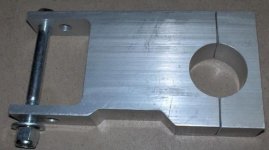
Drive Mounts and Irregular Tubing Shapes

12p3phPMDC

1 kW
Joined
Mar 16, 2009
Messages
462
Here's an idea for matching the profiles on complex tubing shapes i.e. anything
other than a circle.

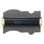
It's called a contour gage. It's easy to use, you just push it against the profile
you are trying to copy and the individual pins slide in the frame and voila...instant copy
of the shape. You can then transfer the layout with a marker or pencil or whatever
to a piece of wood in order to make a pattern.

8 bucks at ACE hardware.

contourgauge.jpg
 
I've also wondered about making a solid mount for oval tubing. If the oval cross-section is 2" X 3", rather than shop for a 4" X 5" cross-section aluminum block and then cutting it in half after shaping the oval hole, I'd get two 2" X 5" aluminum plates. I'd drill and bolt where the bolts will end up, then drill out the two ends of the oval with a small hole-saw, then cut out the center with a larger hole-saw.

The ragged three-hole oval would be oversized, and then I would mount it on the bike, and insert two pieces of manila folder from the front and back inbetween the two plates to separate the left and right voids. I would have waxed the tube in the beginning, and at this point I'd fill the left and right voids with JB-Weld (don't laugh!)

Just an idea, one among many other useful options...
 
re: JB weld.

Not laughing................hard anyway!!! :lol: 8)

But seriously...

If you make an accurate pattern, you can take an inexpensive router table, a carbide pattern following bit, the ones with
bearings on the end and machine aluminum with it.

router_template_bit.jpg

An accurate pattern can produce dovetails for example with accuracy better than 5 thousandths
of an inch....seriously....

1. Copy: Pull the shape with the Contour Gauge

2. Template: Transfer the shape to your template material.. 1/4 to 3/8 ply, masonite, solid wood, plastic whatever.
Cut the oval hole in your template. This step needs to be as accurate as possible because it is the master pattern.
Sneek up on the cut slowly. A scroll saw would be the best thing for this. A suitable jig and a router table
would also allow you to freehand the cut. Of course, all this takes some skill.

3. Machine Mounts : Trace the template onto the mount. Cut the ragged holes undersized using the hole saw.
Overlay and clamp the template to the mount. Slide the assembly over the pattern bit and machine to the pattern.
The bearing will follow the template and you will have exact replica of the pattern (empasize the importance of step 2)

Even if you have CNC capability, the contour gauge will make easy to copy the profile directly off the tube.
You can then scan the drawing, convert to CAM file and now you have the profile. May require a little tweaking,
but you can zero in much faster. kinda of like a poor boys coordinate measuring machine or CMM.

Tapered tubes would with compound curves would be really hard, and the mold method would be easier.

You could make a template with the mold method....no high accuracy machine steps required in making the template
because the mold would be a perfect fit...(saran wrap would be easier than card stock).


router template machining is well documented....

Here's an example for a dremel router, probably better suited for plywood. It uses a collar instead of bearing for
following the template.
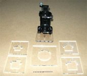
servo_templates.jpg
 
JB weld is rather expensive, maybe auto body filler, 'bondo', would be just as good. I would make the clamp long, so it does not crush the tube. Some AL bikes are pretty thin walled these days.
Bondo is made of micro balloons and fiberglass resin.
 
Along the lines of bondo, there is another body filler that is typically used for filling larger areas that has a high content of fiberglass in it. It is called Long and Strong. Works very similar to bondo, however will hold up alot better in a compression situation. I would probably smear it on, then put the clamp on and let it squeeze out the excess, to avoid air pockets. If you can afford the JB weld method, I think it would give you the best results because it flows really nicely and would require minimal post processing.

--Ryan
 
Might think about broaching.

get a piece of hard steel, cut and grind into the shape of half of the tube. grind clearance on the newly cut broach. mount rigidly in a drill press. mount a piece of aluminum rigidly to the table, pull the broach down the face of the aluminum to start "scraping" the surface away. advance the aluminum forward and broach again. Repeat until half the oval is broached away. Then do the other half in a second piece of aluminum. Fit the two around an oval that matches the bike tube and drill the bolt holes last.
 
Here's a $26 clamp from the Staton site, it looks like theres plenty of meat to cut out most of the shapes someone would want (and of course, trim off the excess after), Page 5 from Staton drive components. Its listed as 6" long, so I'm going to guess the hole is about 1-1/2" dia (its for a "Giant Stiletto" bike)

http://www.staton-inc.com/Results1.asp?Category=21&offset=60
 

Attachments

  • Bike_motor_clamp.jpg
    Bike_motor_clamp.jpg
    22.7 KB · Views: 1,522
This certainly isn't a typical lowcost, DIY solution but it's still interesting none-the-less.

239_010.jpg


A 3D laser scanner could be used to model the profile of an irregular tube shape then a 3D model of custom designed mounting bracket could be made. Once you have a 3D model you then have many more options for getting something made/machined/cast. Of course it would all be terribly expensive for just a couple parts.
 
Back
Top